Joining the Back to the Sides
The braced back is next joined to the top-sides assembly. The sides
must first be shaped to have the correct edge profile to meet the
arched back, just as the edges of the sides had to be shaped to join up
with the arched top. The process of marking and shaping the sides is
largely the same as the process used for the top edge, except that the
arched workboard for the back is used instead of the workboard for the
top (since the archings of the top and back are different), and the
correct side heights need to be met at the end and neck blocks.
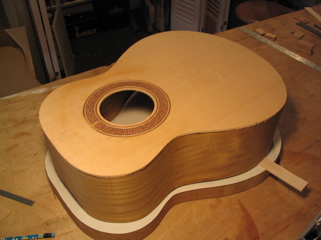
The first step involves marking the side heights at the neck and end
blocks so the completed body will have the desired thicknesses at these
points. In the next two photos, you can see pencil lines indicating
what the finished body thickness is to be at the head and tail of the
guitar. Below the body thickness is marked at the head of the body
(where the neck will attach), in this case 3 1/2".
In the photo below the line marks the side height at the tail of the guitar - in this case, 4".
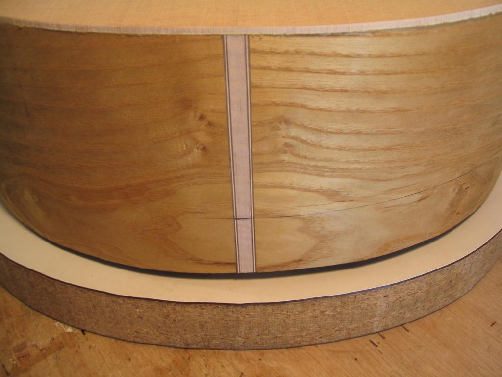
Next the body is placed on the arched back workboard, and shimmed so
that the two pencil marks, at the head and tail of the body, are the
same height off of the workboard. The tail of the guitar is generally
where blocking is needed to raise it up off of the workboard, since the
body is generally thicker at the tail than at the head.
When the assembly has been shimmed so the two pencil marks are the same
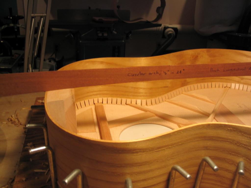
height above the workboard, as drawing gauge is made, consisting of a
thin pice of stck with a 1/16" hole drilled at exactly this height from
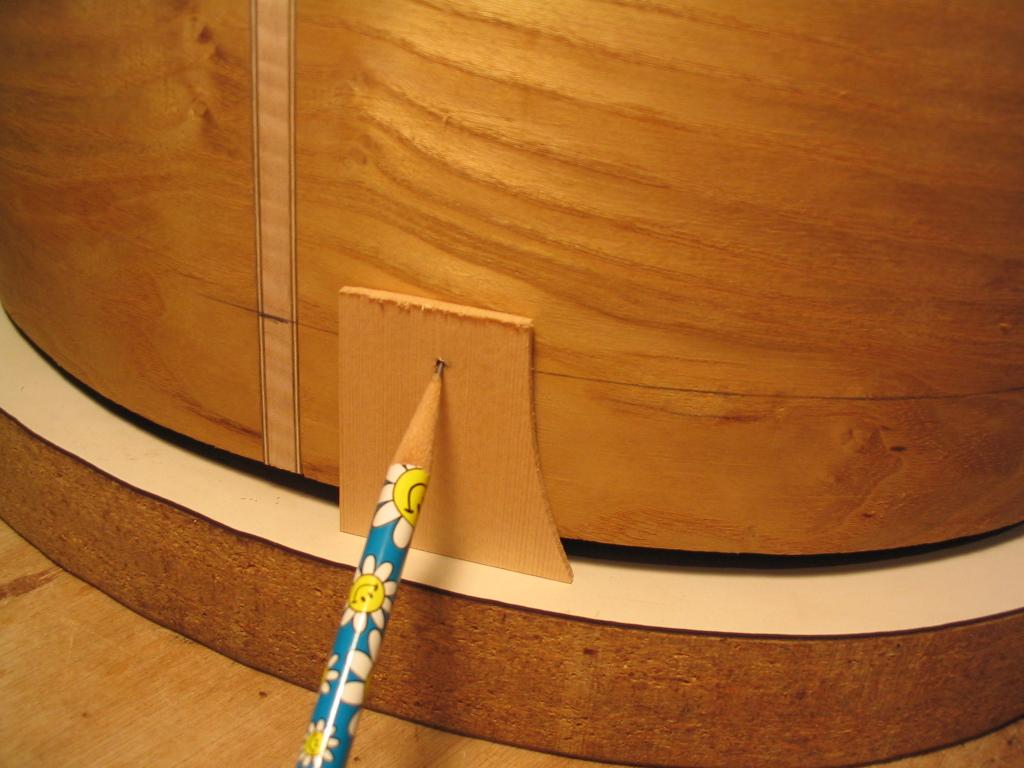
the end, as shown below. This will be used to mark the sides to have
the profile needed to join with the arched back. You can see in the
photo below this gauge with a pencil in the hole. The gauge will be
slid on the workboard around the perimeter of the guitar; since the
workboard has the same arch as the back, the line traced will be gently
undulating to match this arch.
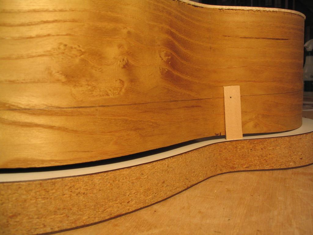
Below you can see the line traced using the gauge, with the gauge in
position (but without the pencil). Note that it's important to keep the
top-side assembly from shifting on the arched workboard as the guage is
used to draw the line.
The line traces the entire periphery of the top-side assembly.
With the back-side profile traced, the sides can now be cut down to
this profile. Since there's a lot of material to remove, I generally
start with a drawknife, as shown below. The top-side assembly is placed
into the gluing form to hold it during this operation. (If this doesn't
hold the assembly securely enough, a waist brace can be put in to
"clamp" the sides in the jig.)
You need to watch the grain while using the drawknife, as it's easy to split off a bigger chaunk than you intended...
In the photo below, the sides have been cut down to within about 1/4"
of the scribed line, except at the neck and end blocks. Since the end
block protrudes significantly, it will be cut with a saw before shaping
proceeds with a spokeshave.
The tail block is rough-sawn with a bowsaw. Note the clamp to help secure the assembly during this operation.
The tail block after sawing - ugly, but easier than trying to
spokeshave all that material off. (Got kind of close to the line,
though...)
Shaping now proceeeds with a spokeshave. This allows fine shaving, to shape the side profile right to the line.
The end and neck blacks need to be tapered so thay'll match the arch of
the back - they're not horizontal on top, but arched slightly. A gauge
cut with the longitudinal arch of the back is used to check the taper
as they're shaved.
Here's a close-up of the taper being checked on the neck block.
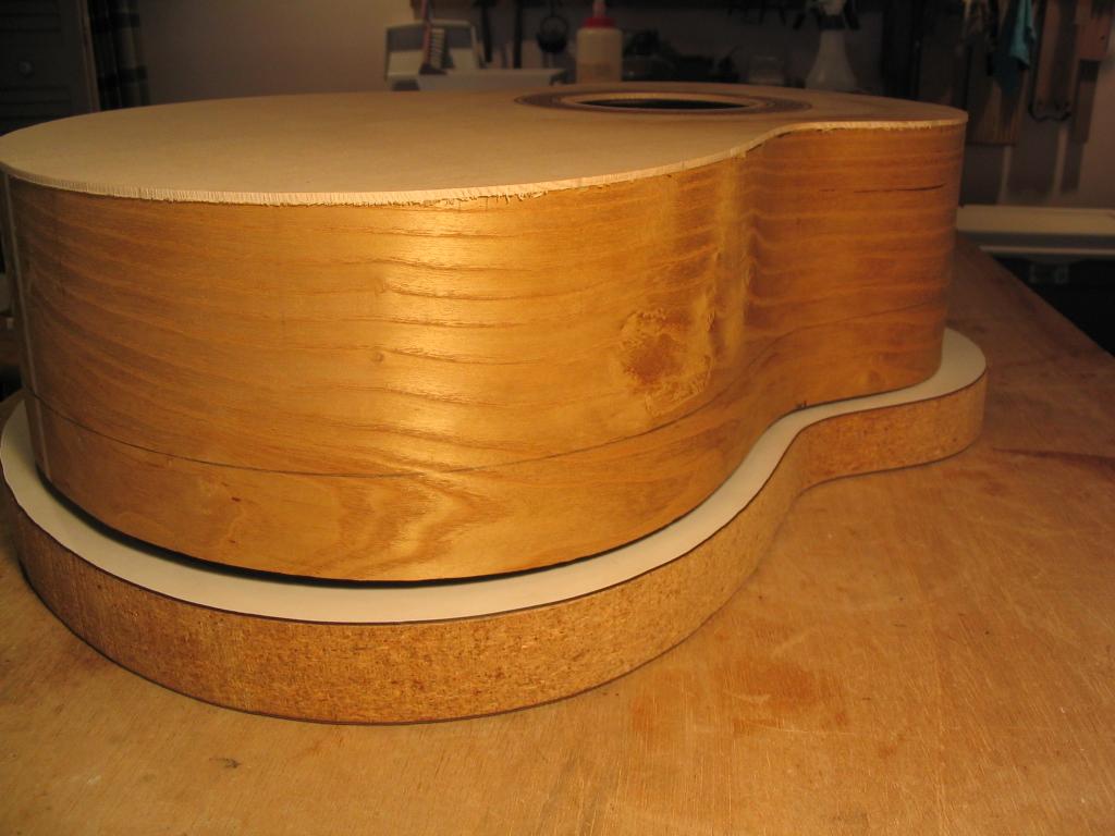
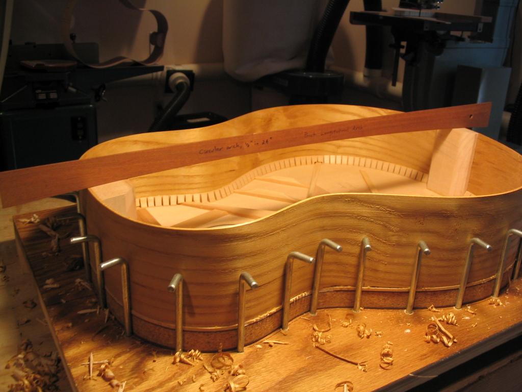
When the side profile has been shaved to the reference line with the
spokeshave, the profile should now match the arched profile of the
back. This is checked by inverting the assembly on the arched
workboard. The assembly should sit evenly on the board, with no gap
showing at any point. If there are significant gaps, the assembly can
be placed back in the jig and shaved further. Note that the fit is less
critical than with the top, since the back is flexible and will conform
to slight irregularities in the profile when it's clamped during
gluing.
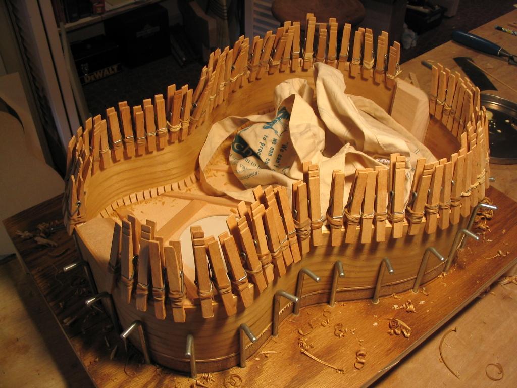
Next kerfing is glued along the edge of the sides, using clothespins
reinforced with rubber bands to give them a little greater clamping
power. Note that as before, the kerfing is glued on so that it sits a
little above the edge of the sides, since it must be shaved to a taper
that matches the arch of the back (as was done with the neck and end
blocks).
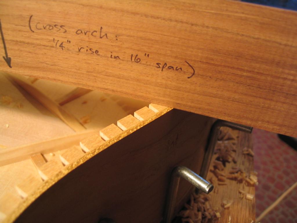
The kerfing is now shaved down to the profile of the sides, but is
angled so that it matches the arch of the back. This angling is checked
with a template that matches the cross arch of the back.
Next side reinforcement strips are glued on. These are thin and narrow
strips of wood glued vertically at intervals along the inside surface
of the sides. These serve to help prevent the sides from cracking due
to an impact. You can just barely see the strip peeking out from
beneath the clamps. The strip that is glued at the waist (shown) must
have its gluing surface scraped to a concave profile so it will fit
flush on the convex surface of the sides at the waist.
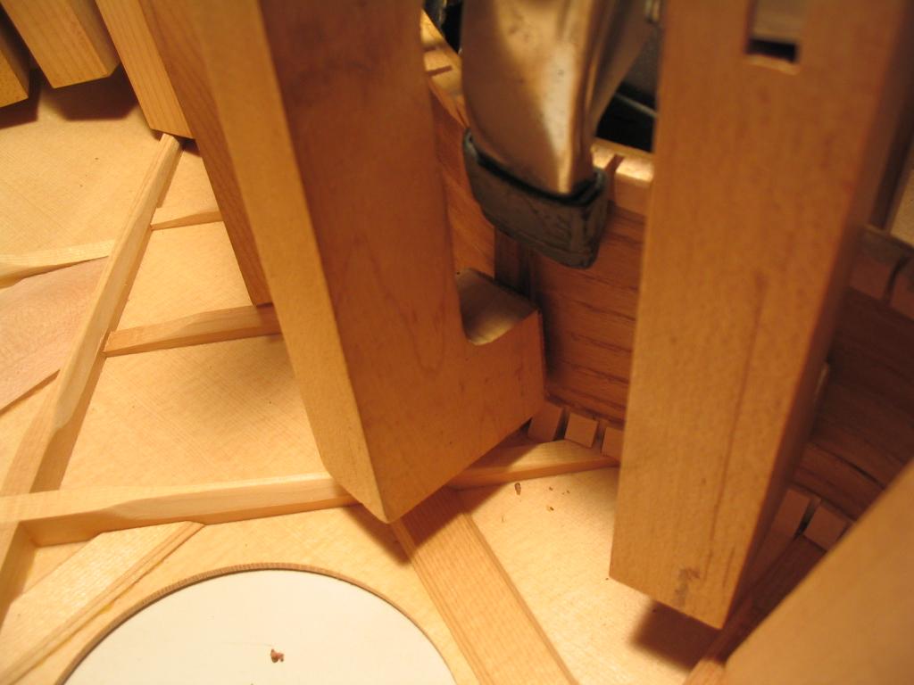
The neck block reinforcement can now be glued on. This is a block that
fits against the neck block and top, and provides additional support
for the portion of the top that will be supporting the fingerboard.
Since the top is arched, the angle formed by the top and the neck block
isn't a right angle, and the block must be planed to the correct angle
to contact both the top and neck block. The reinforcement block is the
maple block below the cherry clamping cauls in the picture below.
The reinforcement block after gluing.
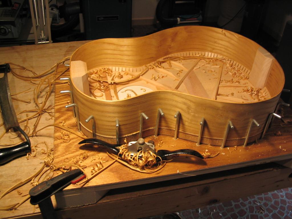
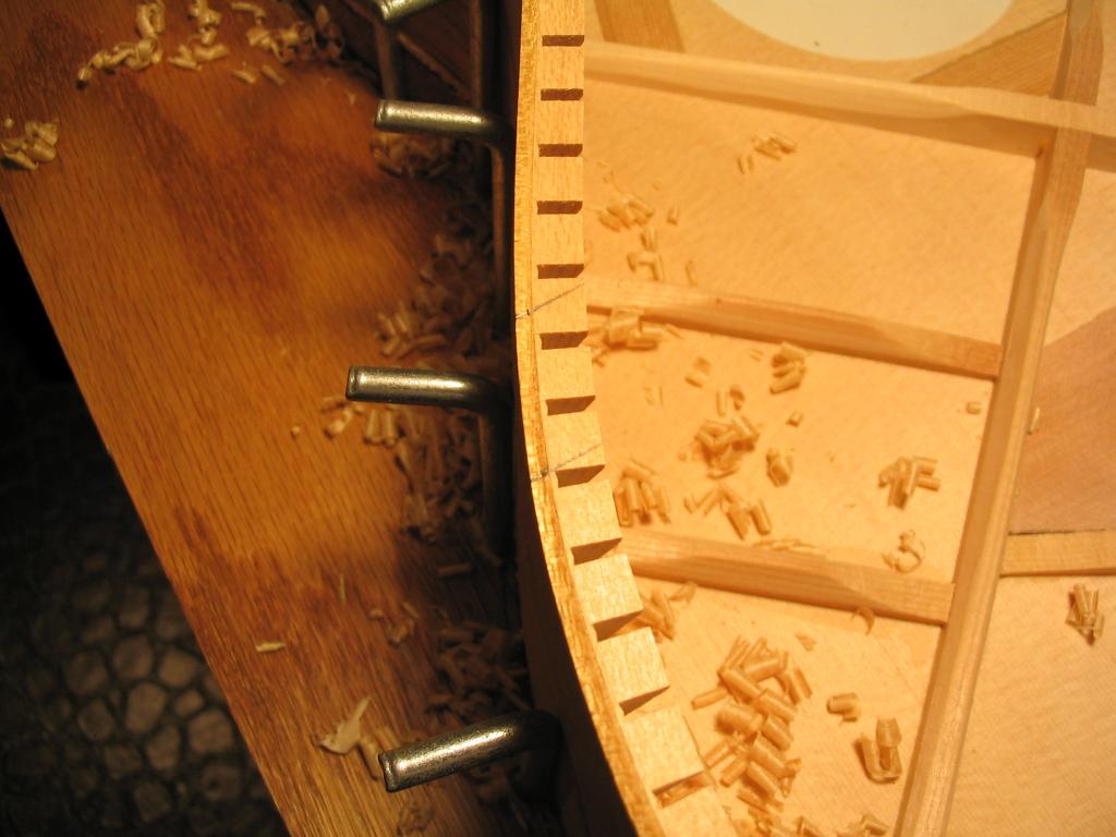
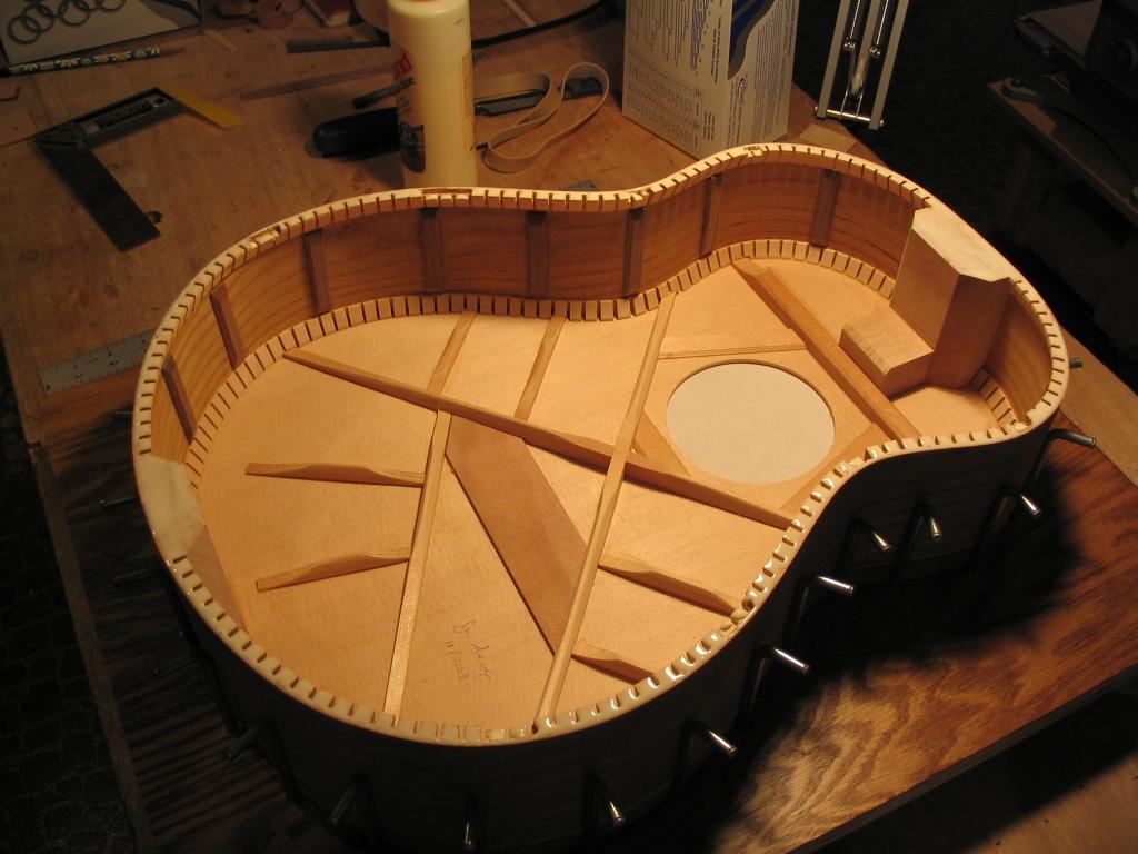
The kerfing must now be notched to accept the back braces where they
meet the sides. The back is placed on the side assembly, and the
position of the braces is marked on the sides.
The brace positions are then transferred to the top surface of the kerfing.
The marked lines are cut with a knife, and the kerfing is then notched
with a sharp chisel in the location of the braces. The depth of the
notches is equal to the height of the braces where they meet the sides.
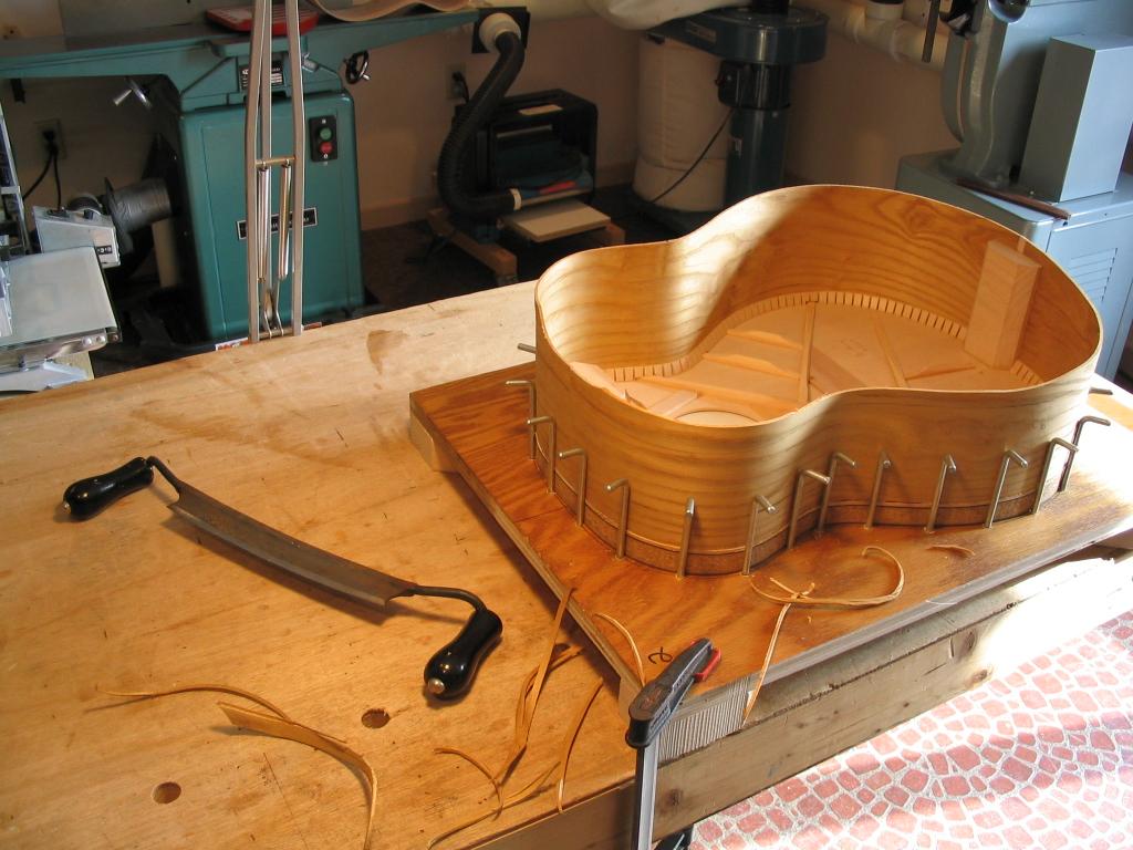
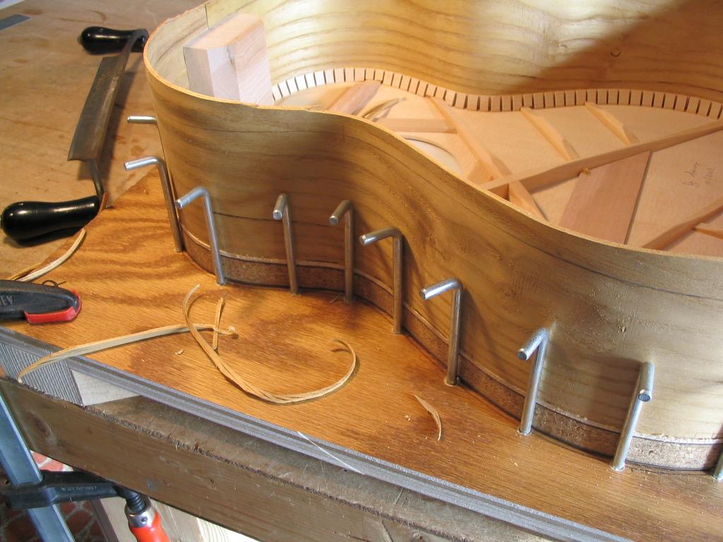
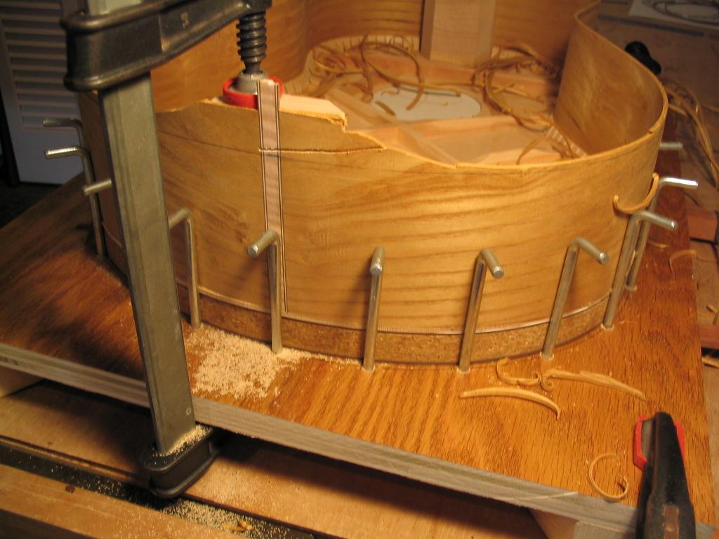
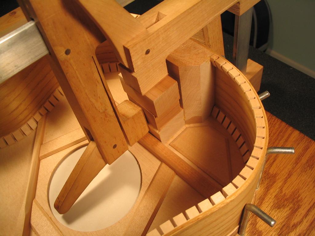
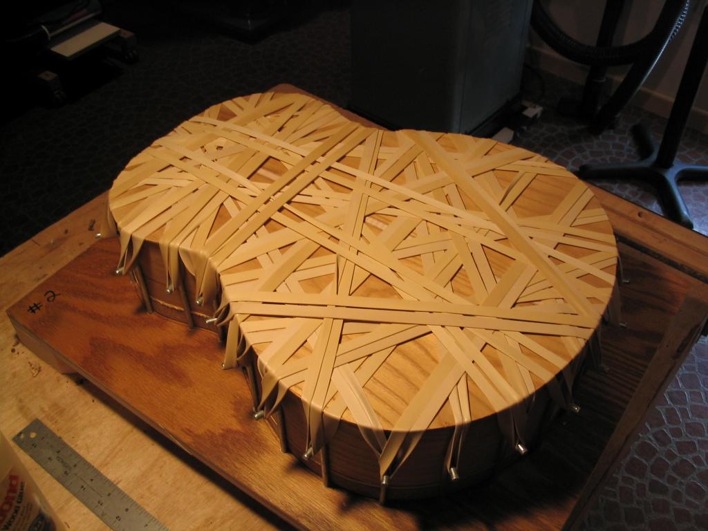
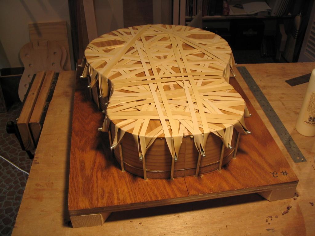
At this point, the back can be glued to the top-side assembly. Glue is
spread evenly on the kerfing and end and neck blocks. The glue should
be applied with care so that it doesn't drip through the gaps in the
kerfing. Glue should also be spread in the notches for the brace ends.
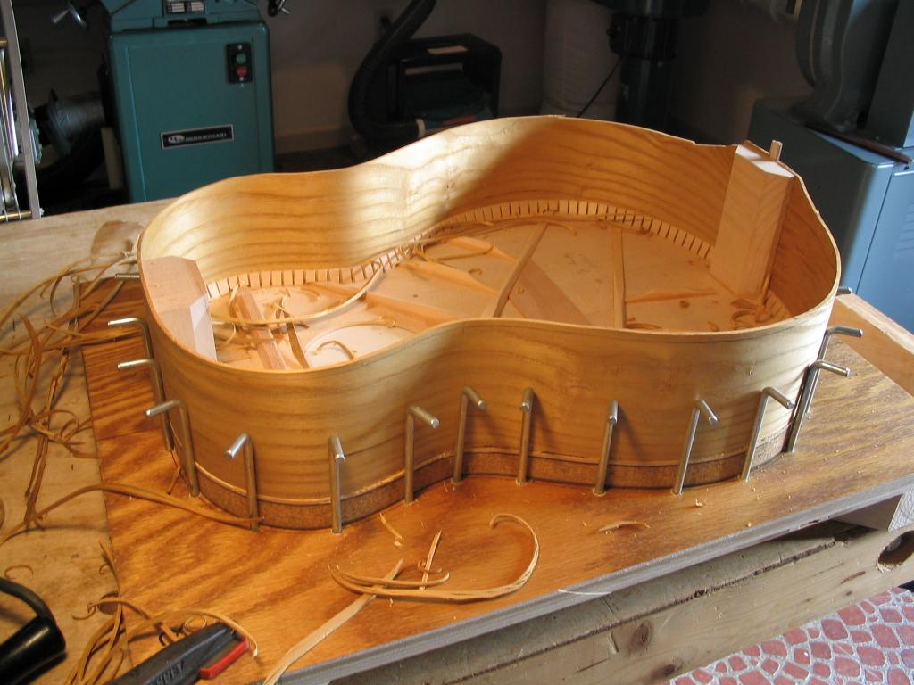
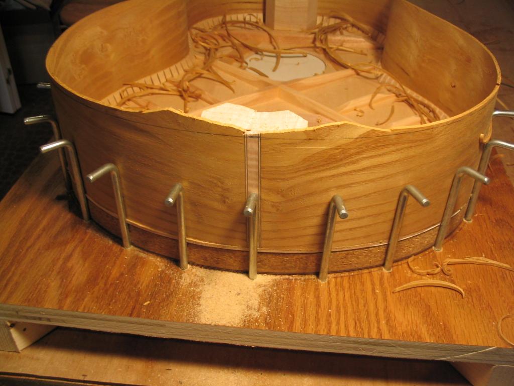
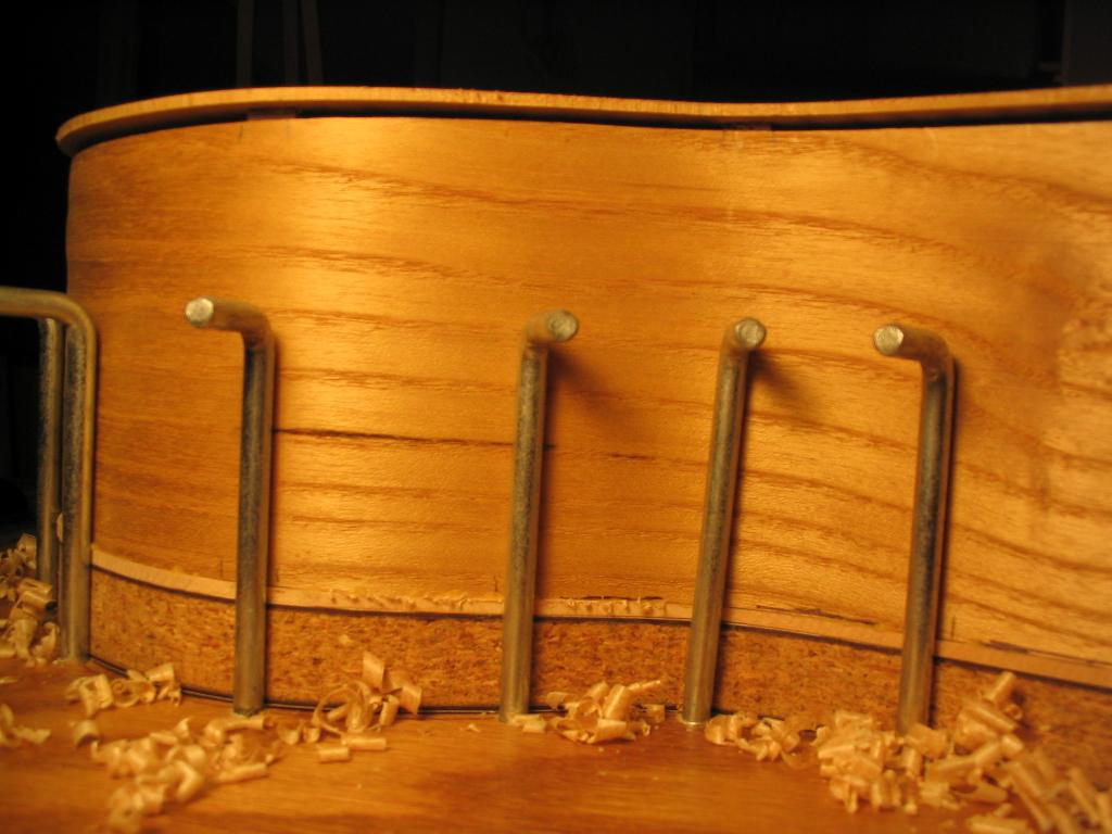
The back is then placed on the assembly, aligned so the binding strip
in the back lines up with the binding strip at the tail. The number 107
rubber bans are then stretched between pairs of "L" hooks on the jig to
apply clamping pressure.
Previous Index Next
Comments/questions: jsevy@cs.drexel.edu