Introduction and Motivation
Inlays are a nice way to customize a guitar. Loosely defined, an inlay is a design consisting of a cutout of one material glued into a recess in another. They’re frequently used on the peghead, to display the name or initials of the builder. They’re also used on the fretboard as fret position markers.
A standard approach to doing any type of inlay is the following:
- Design the inlay (using paper and pencil, or with a computer drawing program)
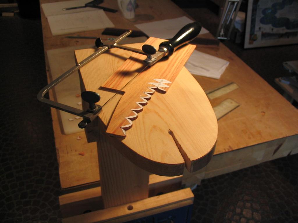
- Cut the design out from the inlay material using a jeweler’s saw and a bird’s-mouth platform
- Scribe the outline of the cut-out pieces onto the surface to be inlaid with an Xacto knife
- Rout the inlay cavities with a Dremel or other small router
- Glue in and sand flush the inlays.
To get good results, very fine precision is needed. For the small-ish designs on a guitar, the design elements need to be cut precisely so they don’t have an uneven appearance, necessitating very fine lines in the design and close cutting to the lines. The routed recesses need to closely match the pieces to be inlaid, requiring precise scribing of the outlines and careful routing under close magnification to make sure there aren’t gaps between the inlays and the pockets. This unfortunately makes the operation tedious and time-consuming, requiring good eyesight and steady hands. As I’ve aged, both of these have gone in the wrong direction. I’ve compensated for aging eyes with multiple layers of magnifying eyepieces, and for the (lack of) fine motor skills with frequent rests. But I’ve been finding that I’m less and less enjoying the process of inlaying – the results, sure, but the work, not so much.
With the advent of inexpensive computer-controlled (CNC) routers, I got to thinking that maybe it would be worth bowing to the inevitable and using technology to help with this aspect of lutherie. Part of me has resisted this sort of automation, as I don’t want to turn my craft into a push-button activity. But we luthiers already use lots of technology, including bandsaws, jointers, thickness sanders and the like, specifically to speed tasks that would otherwise be time-consuming and difficult (you don’t find too many folks resawing their backs and sides by hand any more). So I decided to explore whether the current generation of small, inexpensive CNC routers might be able to give satisfactory results for inlays. I discovered that they can indeed produce very acceptable results, though they have their own learning curve and techniques to master. The following describes how I now use them to do fretboard and peghead inlays.
Hardware
CNC Routers
Inexpensive CNC routers suitable for inlay use are widely available. These provide a router motor suspended above a table, with feed screws and stepper motors that can move the router spindle in the x and y (horizontal) and z (vertical) directions as instructed by commands supplied to an onboard computer. Many have a similar design, and are often denoted by the amount of travel they offer in the two horizontal directions. For example a “3018” model, which I began with, will be able to rout a design within an area 30 cm by 18 cm. In some cases the feed screws move the router motor above a stationary table; in others the table moves beneath a stationary router (like a classical milling machine). The machines I have uses a hybrid approach, where the router motor moves in the x and z directions while the table moves in the y direction. To the end user, it really doesn’t matter which approach is used – the machine will translate movement commands into the appropriate table or router motions.
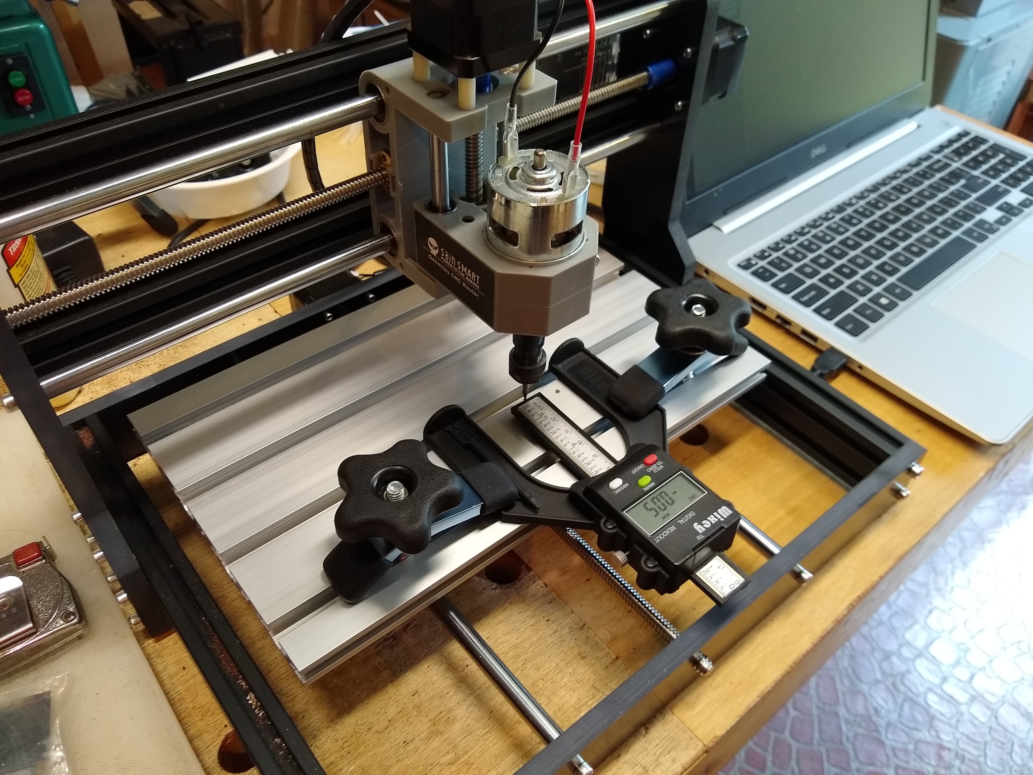
The least expensive models, such as the Genmitsu 3018 Pro used in the illustrations below, typically cost less than $200. These are perfectly adequate for the inlay operations described in this article, capable of giving very nice results with tight-fitting inlays. They can be used for many other operations as well. Their primary limitation is the need to take lighter cuts due to their less robust construction. More expensive models provide more capabilities, such as the ability to make deeper cuts at a higher feed rate and handle tougher materials like aluminum due to the machines’ heavier construction and more powerful motors. They will also tend to be slightly more accurate for inlay work due to their generally having less inherent backlash, though this article gives techniques to reduce the effects of backlash for any machine (discussed at length below). Most notably, these also usually provide a larger cutting area, permitting larger designs to be routed. Neither of these is necessary for inlaying – the smaller and less expensive models work fine for this. I’ve since upgraded to a larger model (the AnoleX 3030-Evo Max), and have found it to be a useful upgrade, both for its ability to cut inlays somewhat faster (though the feed rate is primarily limited by the strength of the small-diameter bits used in inlaying) and slightly more accurately, and its utility in creating jigs from plexiglass. But the inexpensive 3018 model I used previously and illustrated below gives very good results for inlays in lutherie.
Router Control: G-code
CNC routers are controlled by sending commands through an attached computer using router control software, discussed below. The commands are in a standard format called “g-code”. This is a simple text-based language used to specify a sequence of motions; it’s called g-code because most of the commands begin with a letter G. For example, the command
G21
tells the machine to interpret all the values that follows in millimeters, and the command
G00 X10 Y-10
tells the machine to move the router bit by 10 mm in the X direction and -10 mm in the Y direction. There are lots of other commands to create things like circular arcs and even B-splines. Fortunately, you don’t need to know any of this to use a CNC router. The software used in the design process takes care of generating g-code behind the scenes, and the control software transmits this to the router.
Cutting Bits
Cutting bits are needed to go into the cutting head of the CNC router. For inlaying, these are usually end mills, which means they cut flat-bottomed slots. There are many varieties available, in many different diameters and different flute configurations (straight, spiral). I’ve found that for cutting mother of pearl and abalone, a high-quality 2- or 4-flute solid carbide spiral bit works well, in diameters of 1/16″ (0.0625″) and 1/32″ (0.03125″). These are also suitable for cutting hardwood (rosewood, maple, etc.), though a bit with 2 flutes helps provide a little more chip clearance. The quality of the bits matters; I’ve had success with the Speed Tiger and uxcell brand bits through Amazon. But bits do break, especially when you’re first learning a machine’s capabilities, so it’s important to have a good supply on hand.
Software
Several software packages are used to produce inlays on a CNC router.
Design Software
This is software used to create the desired inlay shape. Any basic computer drawing package will do – I use the free and open-source LibreOffice Draw program. This allows me to use lines, arcs, polygons and Bezier curves to create and tweak the design I want for the inlay. I use this for designing both my initials for the peghead inlay and fretmarker inlays for the fretboard, both for manual inlays and those done with the CNC router.
I use a second open-source package, Inkscape, to further prepare the design for inlaying with the CNC router. Inkscape is a vector-graphics package. This works on designs in what’s known as SVG, or Scalable Vector Graphics, format. Where basic drawing packages represent a design as a series of discrete lines and curves, the SVG format can combine these together into a single path representing the closed outline of a shape. It’s this sort of closed path that’s needed to generate a sequence of g-code bit-movement instructions used by the CNC router. Thus I first create a design using LibreOffice Draw, and then convert it to SVG format using Inkscape.
G-code Generation Software
The software that I use to generate g-code instructions for the CNC router from an SVG path is JSCut Inlay Assistant, a modified version of the wonderful web-based software package JSCut. This is a nifty free web-based package that does a number of things needed to successfully drive the CNC router. It will take a path you’ve supplied and generate a sequence of g-code movements that mirror that path. For an inlay, you need two separate sets of g-code instructions: one to cut out the inlay from the inlay material (mother of pearl, say), and another to cut the recess or pocket into the peghead or fretboard to receive the inlay. However, you generally don’t want the bit to just travel directly over the center of the design line. In both cases, you need to offset from the path by the radius of the cutting bit, outside for the inlay and inside for the pocket. Additionally, for the pocket, you need to rout out not just the outline, but also the material inside the shape. JSCut Inlay Assistant takes care of all of these, and additionally sequences operations in a way to optimize the fit of the inlay in the recess.
Router Control Software
The final software needed is software to directly interface with the router. This software generally provides both manual control over the router, allowing the user to directly move (or “jog”) the router bit by a specified amount in the x, y, and z directions, and the ability to download g-code created in the design process to be run automatically by the machine to cut inlay outlines and pockets.
Basic Workflow
The following describes the basic steps used to cut inlays and their corresponding recesses with a CNC router for initials inlaid into a guitar peghead overlay. While this basic approach achieves the main objective, there are some subtleties and easy improvements discussed in the next section that help to greatly improve the results. But first, the basics.
Design
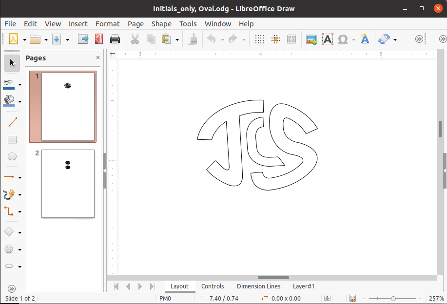
The first step is to create a design for the inlay. As mentioned, I typically use LibreOffice Draw for this. Here’s a screenshot of my initials as designed in LibreOffice. These are designed using Bezier curves and straight line segments, both of which are supported in LibreOffice and most other computer drawing packages (Visio, etc.)
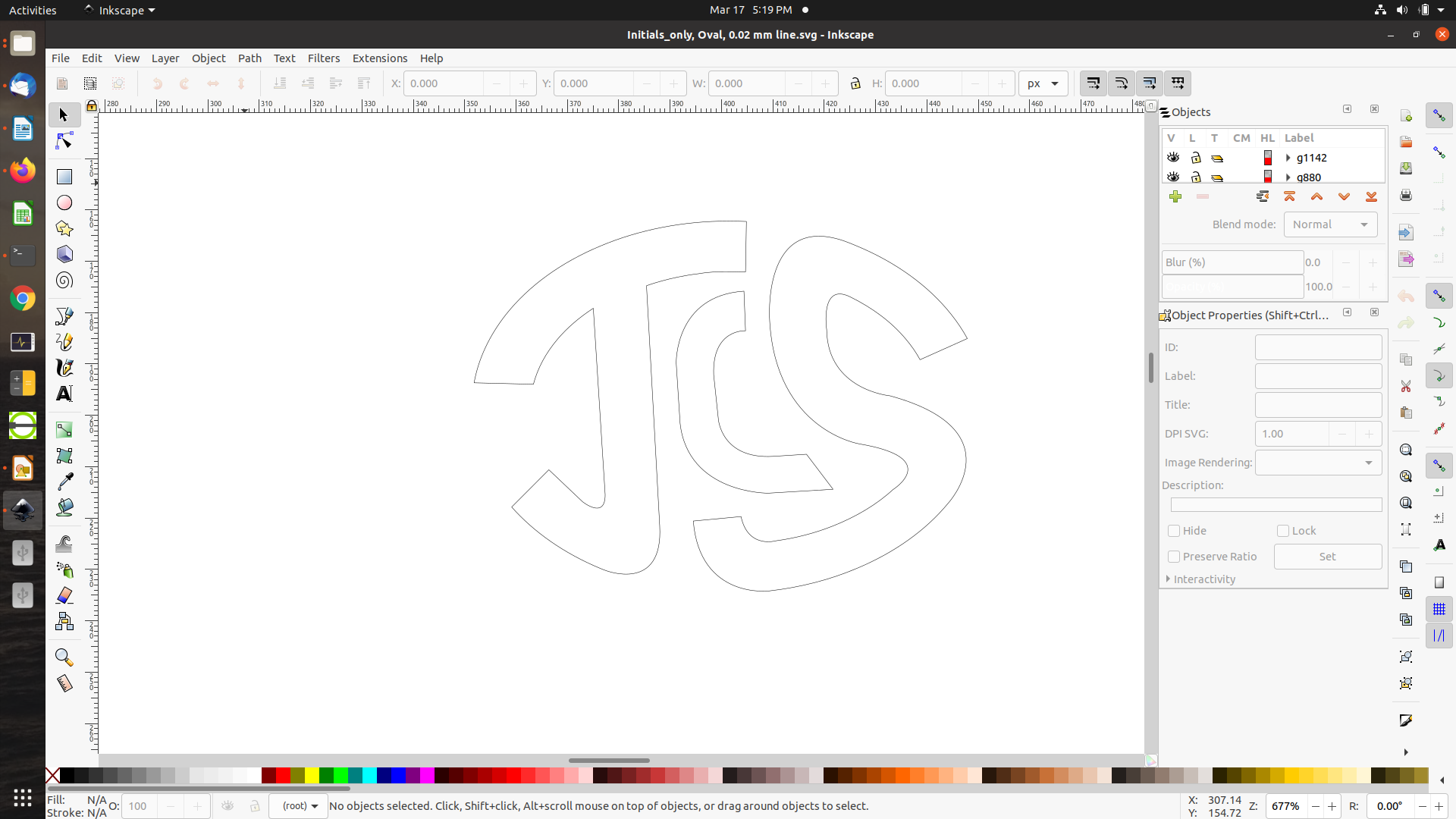
This design is saved in the standard LibreOffice ODG format. However, to be used to generate the g-code used to drive the router, the design first needs to be turned into SVG (Structured Vector Graphics) format. This is accomplished by importing the .odg file into the Inkscape package and saving it as a .svg file. Here are the initials as they appear in Inkscape. Note that Inkscape itself can be used as a design package and the design saved directly in SVG format; I just prefer LibreOffice Draw as my drawing platform.
One twist is that the outlines need to be continuous SVG “paths”. During design, the outlines are often created from discrete elements like line segments, circular arcs, Bezier curves, and the like. Though they appear visually continuous when you draw curves so that their endpoints coincide, they’re still viewed as separate elements by the software. Thus it will often be necessary to perform an operation that explicitly joins the endpoints of the separate curve segments to create a continuous SVG path. Inkscape provides this capability through Path Operations and the Node tool, which are described in the Inkscape documentation.
G-code Generation
The SVG design then needs to be turned into a sequence of g-code commands for control of the router. This is done by the JSCut Inlay Assistant program, which takes an SVG file as input and generates g-code as output. JSCut Inlay Assistant runs directly in a web browser – there’s no need to install software, just open the URL https://jsevy.com/wordpress/index.php/lutherie/jscut-inlay-assistant/ in your web browser of choice (I use Mozilla Firefox). The initial screen is shown below:
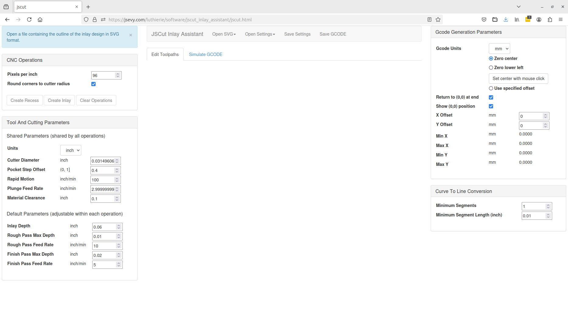
There are some parameters here that are of key importance in generating the g-code for inlays, seen in the panel on the left side of the window. These need to be set correctly to get g-code that will successfully cut the inlay.
The first is the diameter of the cutter to be used, which for my purposes I have set to 0.8 mm, or approximately 1/32″. You’d obviously set this to a different value depending on the bits you have available. Considerations on bit size selection include the delicateness of the design (the bit needs to be smaller than the minimum width of channel that needs to be cut) and the sharpness of inside corners (which otherwise will need to be cleaned up by hand if the bit radius is too large). The cutter diameter is important in the generation of the g-code because the cutter path needs to be offset by the radius of the cutter, outside for the inlay and inside for the recess; this is done automatically by the JSCut Inlay Assistant software.
Other important parameters are the depth of cut to be used for each pass and the speed with which the bit is moved through the material, called the feed rate. Just as with a hand-held router, there’s a limit to how deep you want to cut with each pass and how fast you want to push the bit. The maximum depth of cut and cut speed are interrelated and depend on several things:
- The hardness of the material (e.g., rosewood vs mother of pearl)
- The strength of the stepper motors which drive the cutting head and the overall rigidity of the machine’s construction
- The diameter of the bit used (bigger bits, being stronger, are able to cut deeper and faster without risking bit breakage)
This is an area where some experimentation will be needed. While you can find very helpful tables and recommendations for depth of cut and cut speed based on bit diameter and material, you’ll have to test on your specific CNC router to see if the machine is up to it. Experimentation is key to getting good results.
A great source of information is the PreciseBits website, which sells very high quality bits for cutting shell. The website provides a table of cut depths and feed rates for various size bits for cutting shell, which is one of the more challenging materials to cut due to its hardness. Because their data is for a spindle speed of 24000 rpm, I had to adapt the info for my machine, which has a 7000 rpm max speed with the stock spindle.
Here are settings that have worked for me for mother of pearl and rosewood. Note that there are two sets of parameters here – one for the initial rough pass, and one for the finishing cut. JSCut Inlay Assistant creates a tool path that gets followed twice, once to remove the bulk of the material (the rough cut) and once to trim the edges (the finishing cut). The rough pass is taking the bulk of the material off, so the depth of cut needs to be less. The finishing cut is just trimming the walls of the inlay or outline, so can cut deeper with each pass, though the feed rate is often slower to ensure precision. Additionally, these cuts must be made in the correct direction (clockwise or counterclockwise, depending on whether it’s the rough cut or the finish cut and whether it’s the inlay or the recess). This is in fact the key to getting a tight-fitting inlay, as discussed below in the Appendix. However, you don’t need to worry about this, as the JSCut Inlay Assistant automatically takes care of this in the generated g-code.
Shell (mother of pearl, abalone)
| Rough cut | Finish cut | |||
| Bit diameter (in) | Cut depth per pass (in) | Feed rate (in/min) | Cut depth per pass (in) | Feed rate (in/min) |
| 1/16 (0.0625) | 0.010 | 10 | 0.030 | 5 |
| 1/32 (0.03125) | 0.010 | 10 | 0.020 | 5 |
Rosewood
| Rough cut | Finish cut | |||
| Bit diameter (in) | Cut depth per pass (in) | Feed rate (in/min) | Cut depth per pass (in) | Feed rate (in/min) |
| 1/16 (0.0625) | 0.030 | 10 | 0.060 | 5 |
| 1/32 (0.03125) | 0.020 | 10 | 0.030 | 5 |
The general approach to using JSCut Inlay Assistant is as follows. First, set the parameters for the cut (bit diameter, max cut depth and feed rate for both rough and finish cuts) for the material to be cut (perhaps shell for the inlay, and rosewood for the pocket).
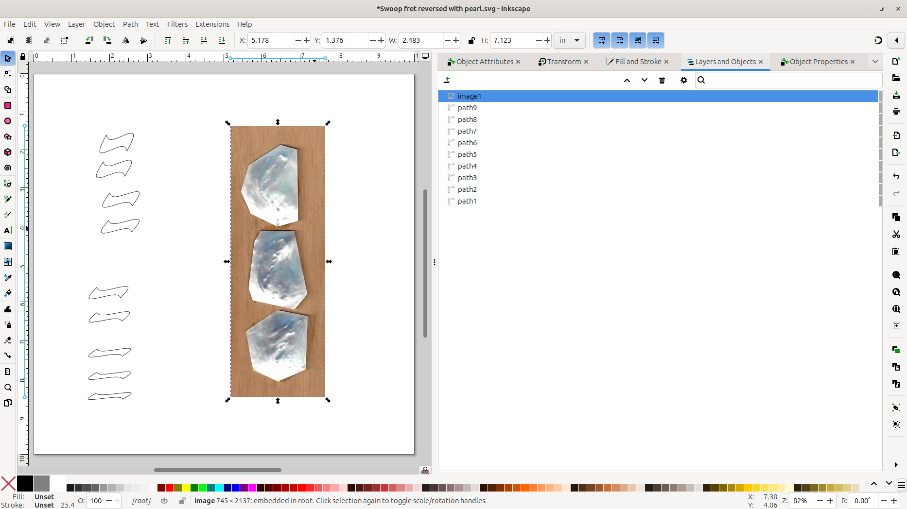
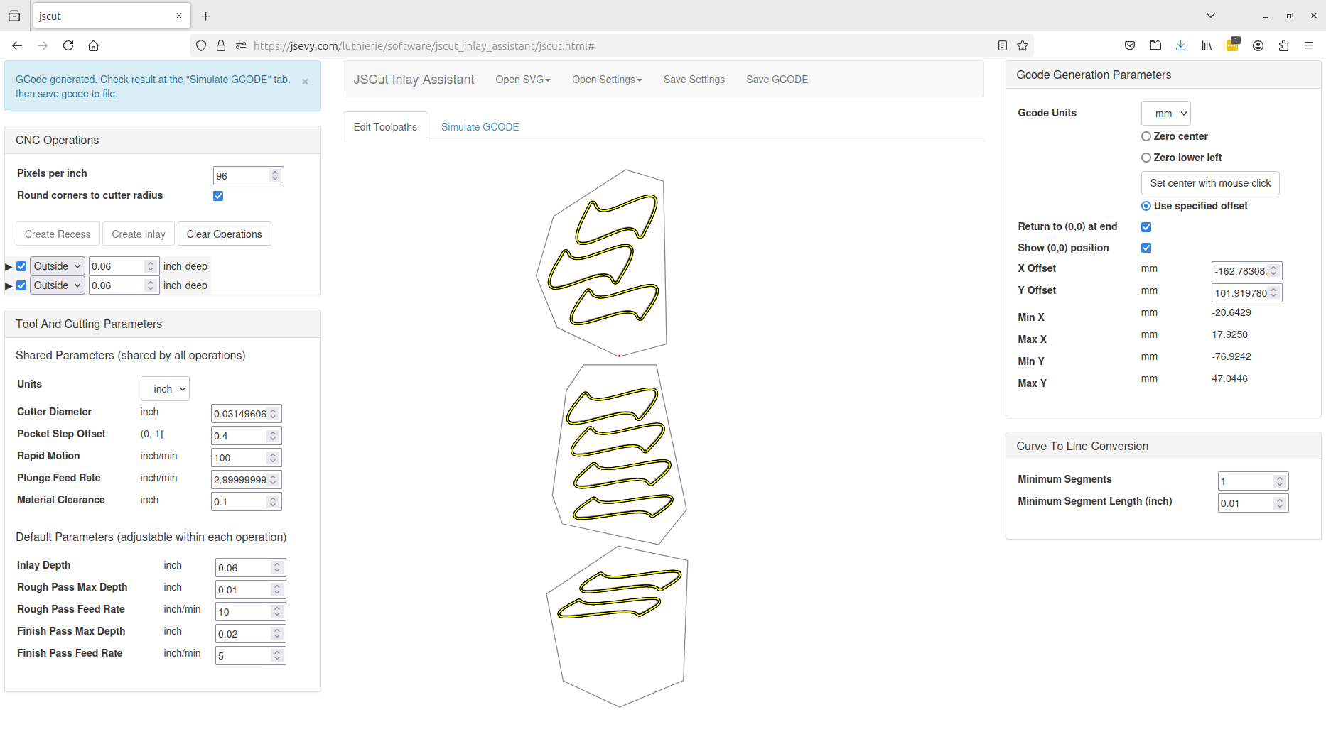
Then the “Open SVG…” button is used to open the SVG file containing the design:
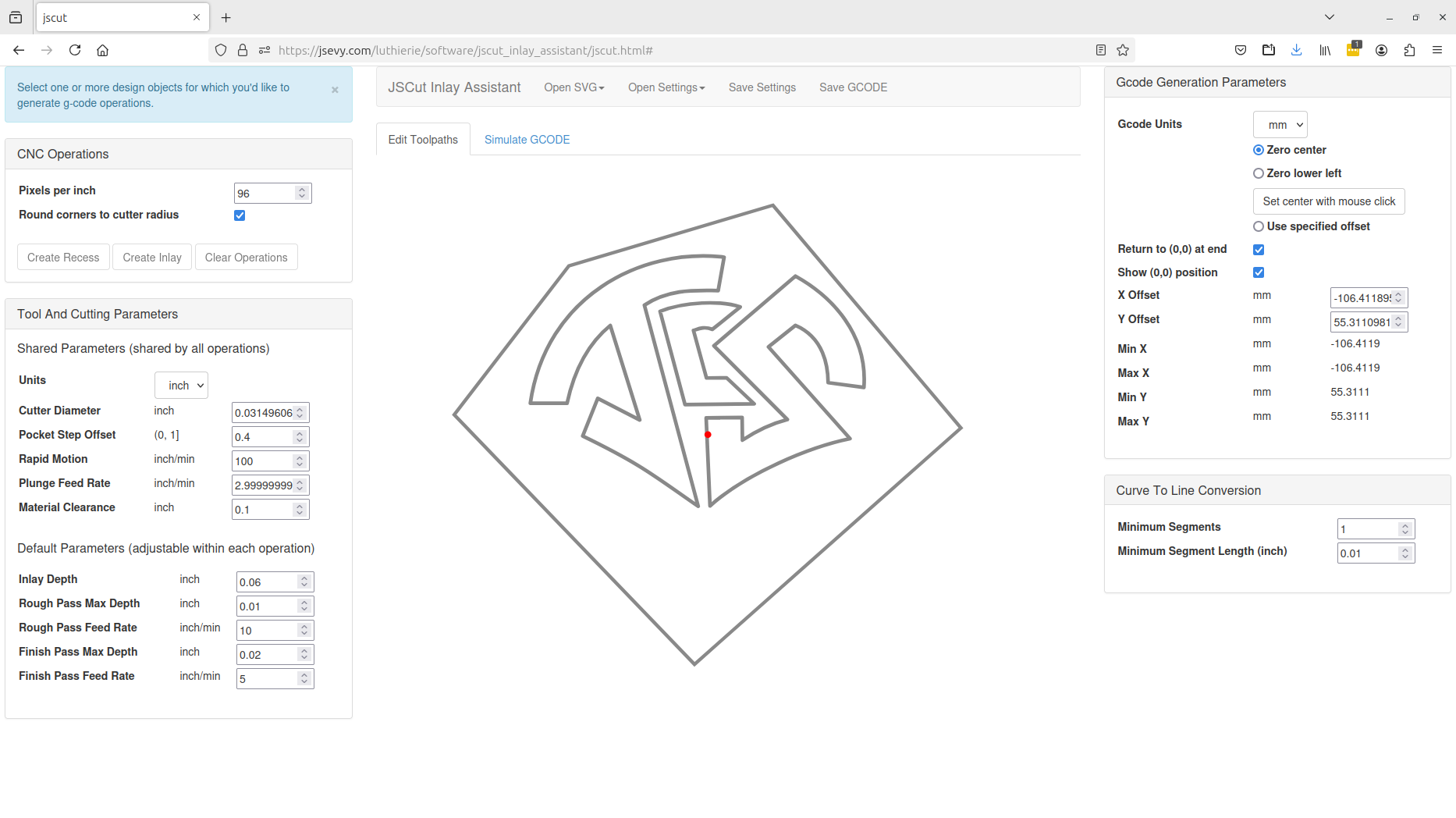
(Note that this particular SVG file has both the initials for the inlay, as well as the outline of the pearl piece the inlay will be cut from, as discussed in more detail later.)
To create g-code for an operation, you need to select (click on) the boundaries of the design to specify which profiles are to be cut. In the following, all of the initials have been selected:

Next the desired operation must be selected. JSCut Inlay Assistant provides two main operations: “Create Inlay”, and “Create Recess”.
Create Inlay
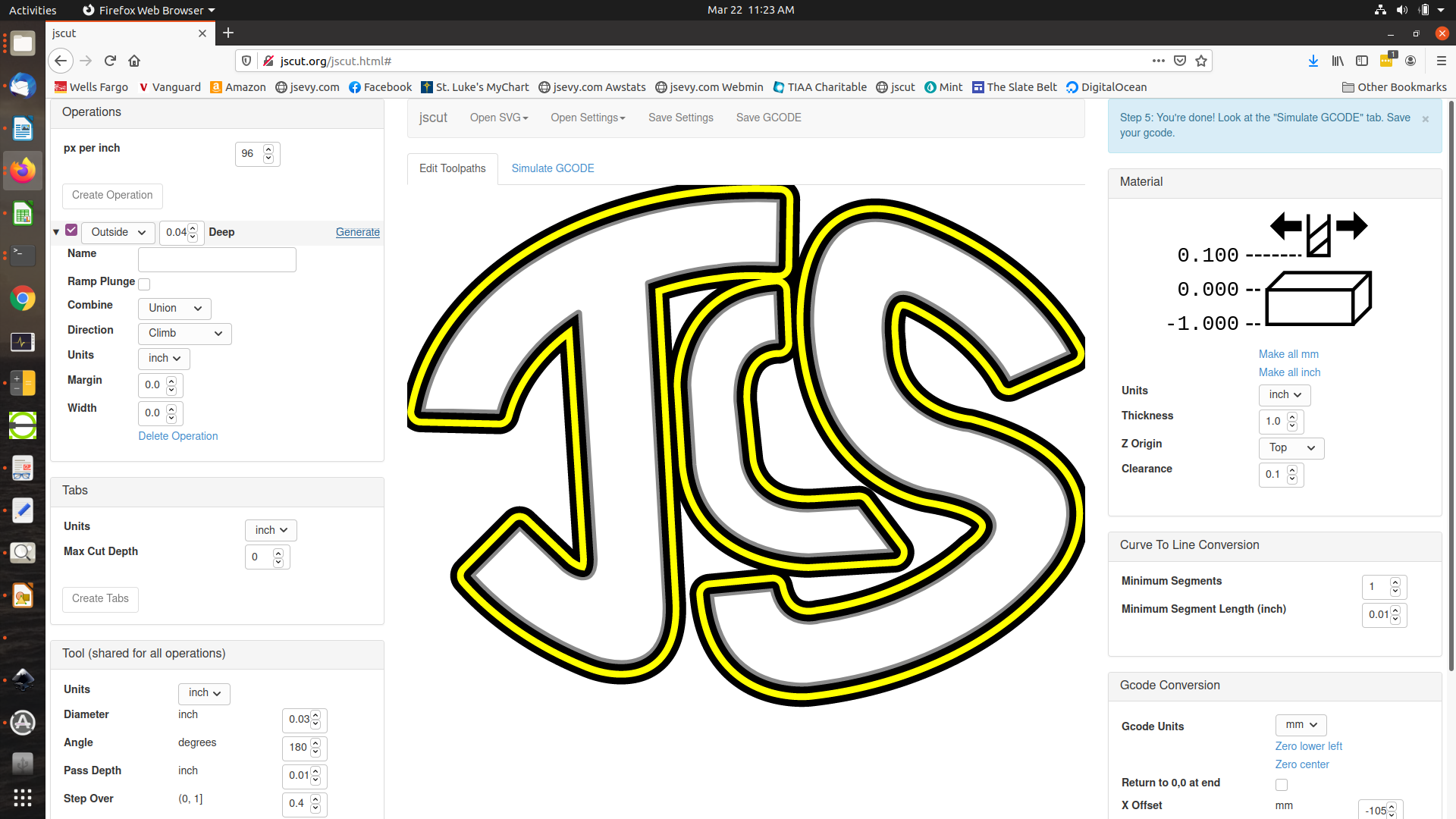
“Create Inlay” generates g-code to drive the cutter around the outline of the design, to cut out the pieces from the pearl for inlaying into a recess. The router will be instructed to cut around the outside boundary of the design, offset by the radius of the cutting bit. The total depth of the cut is specified, generally the thickness of the inlay material (maybe 0.040″ or 0.060″ for mother of pearl and abalone). JSCut will then create a cutting path that traces the design multiple times if needed, with each pass deepening the cut by the specified maximum depth of cut. So for 0.040″ thick shell and a 0.010″ maximum depth of cut, four passes will be generated at increasing depths. It additionally does both a rough cut and then a final cut – the reason for this is discussed below. But you really don’t need to know the details – JSCut Inlay Assistant does this all for you. Below is the screen after “Create Inlay” has been selected for the chosen initials:
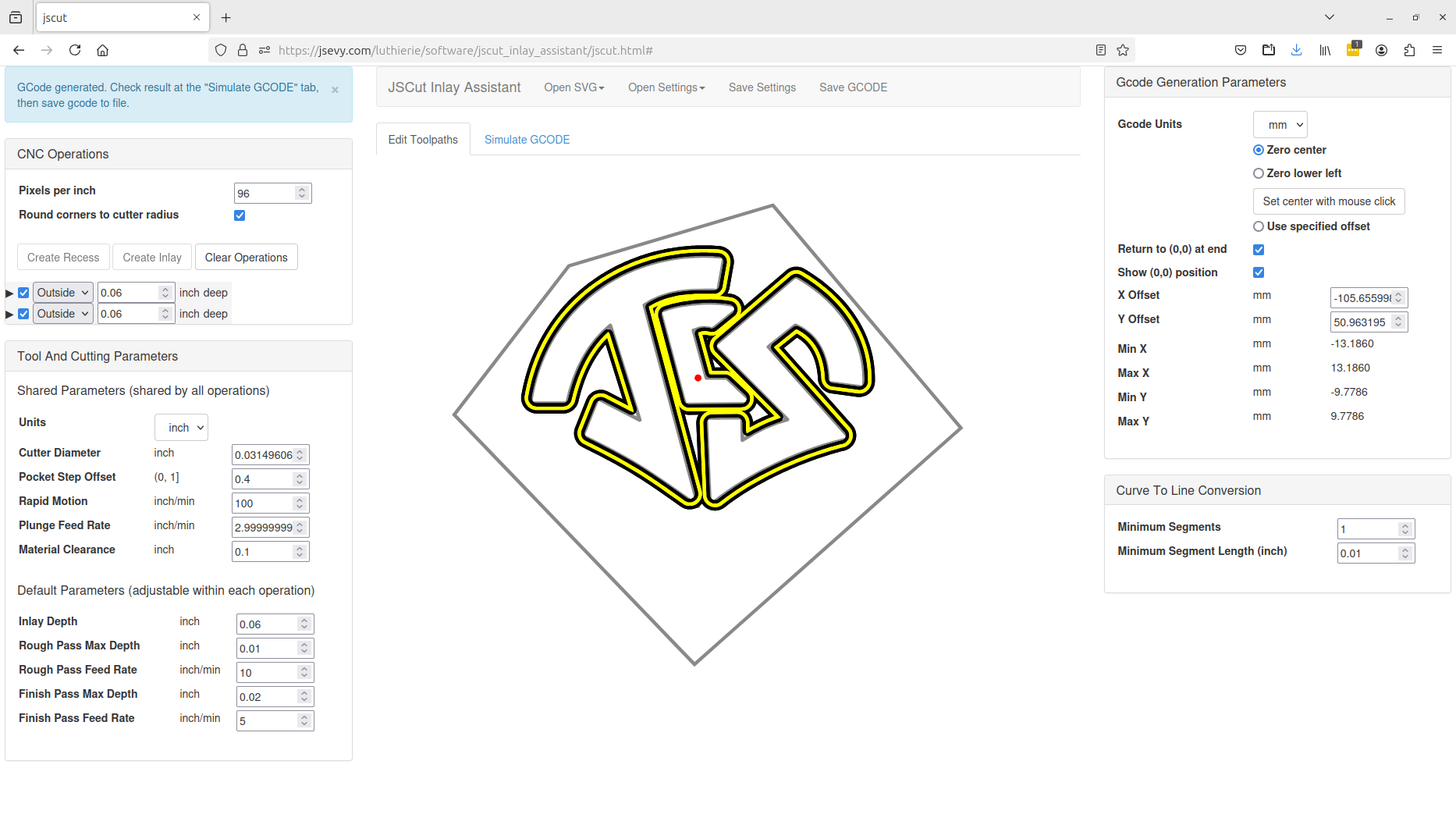
The yellow path shows the path that the cutter will take to cut out the outline of the initials.
A couple of things are worth noting. First, if you zoom in, you can see that the corners of the inlay, both inside and outside, have been rounded off to the radius of the cutter. This occurs when the “Round corners to cutter radius” box at the upper left is selected. This is a convenience feature which makes it easier to fit the inlays into the recess. Without this box being checked, the outside corners of the inlay will be cut sharp. However, since the cutter has a finite radius, the inside corners of the inlay will be rounded. Correspondingly, the outside corners of the recess will be rounded, while the inside corners will be sharp. To fit the sharp inlay corners into the rounded recess corners will require doing some cleanup on the recess corners with a knife or chisel to make them sharp. Similarly, the rounded inside corners of the inlay will need to be trimmed with a file to fit into the sharp inside corners of the recess. To avoid having to do this finish work on the corners, checking the “Round corners to cutter radius” box rounds all of the “sharp” corners to the cutter radius so the inlay will fit into the recess without trimming. Of course, you may want true sharp corners, in which case you’d leave this box unchecked and do the necessary trimming after the router cuts.
Secondly, you can see a red dot on the design. This is the location of the zero point or origin for the cutter. The origin location on the workpiece is set manually on the router before cutting starts. For the pearl piece whose outline is shown, we would need to zero the router to the specified point, which is somewhat arbitrary. A better approach is to set the zero point to one of the corners on the pearl piece, since this is easier to align the router to. The controls on the top right of the screen permit this point to be selected. The two most useful selections are the “Zero center” radio button and the “Set center with mouse click” button. “Zero center” is selected in the screen above, and you can see that the red dot is in the center of the selected initials. Instead, we can select the top corner of the pearl piece as a better reference point; note that this needs to be done before selecting the “Create Inlay” operation. So selecting “Clear Operations” to clear out the operations, then clicking the “Set center with mouse click” button, and clicking on the top corner of the pearl outline leaves the following:
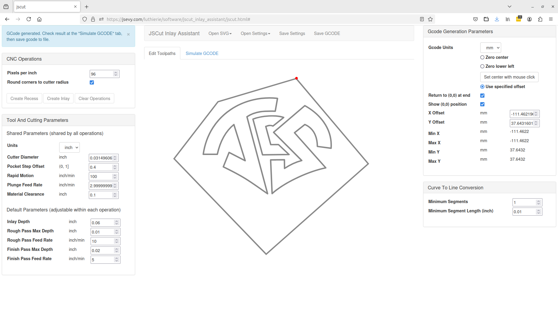
Then selecting the initials and choosing “Create Inlay” gives the following:
 The g-code has now been generated so the machine zero-point is expected to be at the top corner of the pearl. The first step in setup for routing after the piece is clamped to the router is to set this point using the router control software.
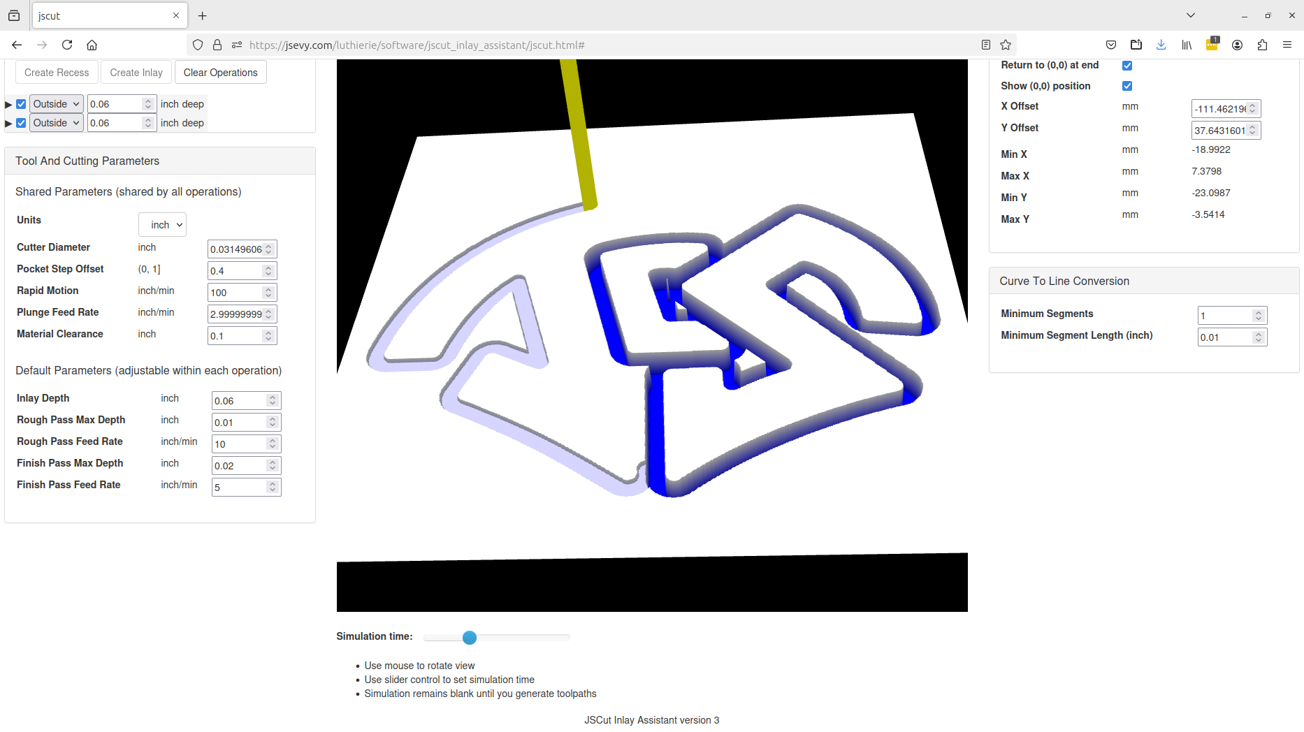
One very nice feature of JSCut Inlay Assistant, inherited from the original JSCut program, is a simulator that shows the path the cutter will take as it cuts out the design. You can watch as the path is traced out and successively deepened. In this way you can see exactly what the router will be instructed to do by the generated g-code. This is especially helpful in ensuring the center (zero-point) is where you expect it to be.
The g-code can then be saved by selecting the “Save GCODE” menu item. This generates the file that will be used to drive the router. It’s traditional to save the file with the suffix “.gcode”. The file is just a plain text file containing the g-code instructions for the router; you can open it with any text editor to see the contents. (You can modify it as well with the text editor, though you’ll want to know what you’re doing before changing any of the instructions that drive the hardware.)
The first few lines of the file saved above are shown below.
G21 ; Set units to mm
G90 ; Absolute positioning
G1 Z2.54 F2540 ; Move to clearance level

;
; Operation: 0
; Name: Rough outside cut (climb)
; Type: Outside
; Paths: 3
; Direction: Climb
; Bit diameter: 0.800 mm
; Cut Depth: 1.52 mm
; Pass Depth: 0.254 mm
; Passes: 6
; Cut rate: 254 mm/min
; Plunge rate: 76.2 mm/min
;

; Path 0
; Rapid to initial position
G1 X3.0684 Y-19.1891 F2540
G1 Z0.0000
; plunge
G1 Z-0.2540 F76.19999999999999
; cut
G1 X2.8927 Y-19.2518 F254
G1 X2.7273 Y-19.3120
G1 X2.7194 Y-19.3151
G1 X2.5419 Y-19.3811
G1 X2.3618 Y-19.4497
G1 X2.1830 Y-19.5190
G1 X2.0093 Y-19.5876
G1 X1.8177 Y-19.6643
G1 X1.8124 Y-19.6661
G-code is a pretty simple language. Everything following a semicolon on a line is a comment, giving human-readable information about the file’s contents. The lines beginning with “G” are instructions for the machine – this is where the name “g-code” comes from. Each line is a separate instruction for the machine to do something – usually move in a straight line. For example, the line
G1 X2.7273 Y-19.3120
instructs the machine to move to the location X = 2.7273 mm and Y = -19.3120 mm. G-code files generally consist of a lot of tiny linear moves like this that approximate the curved outlines of a design.
Create Recess
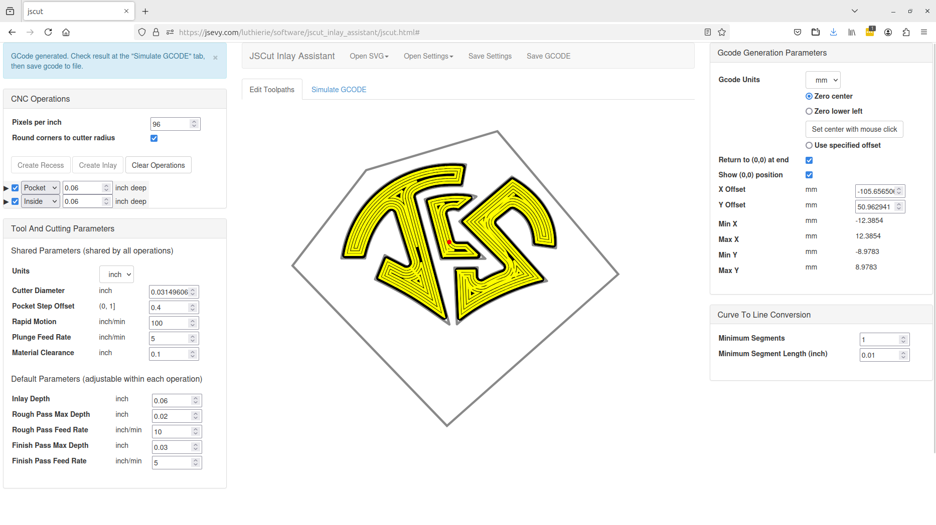
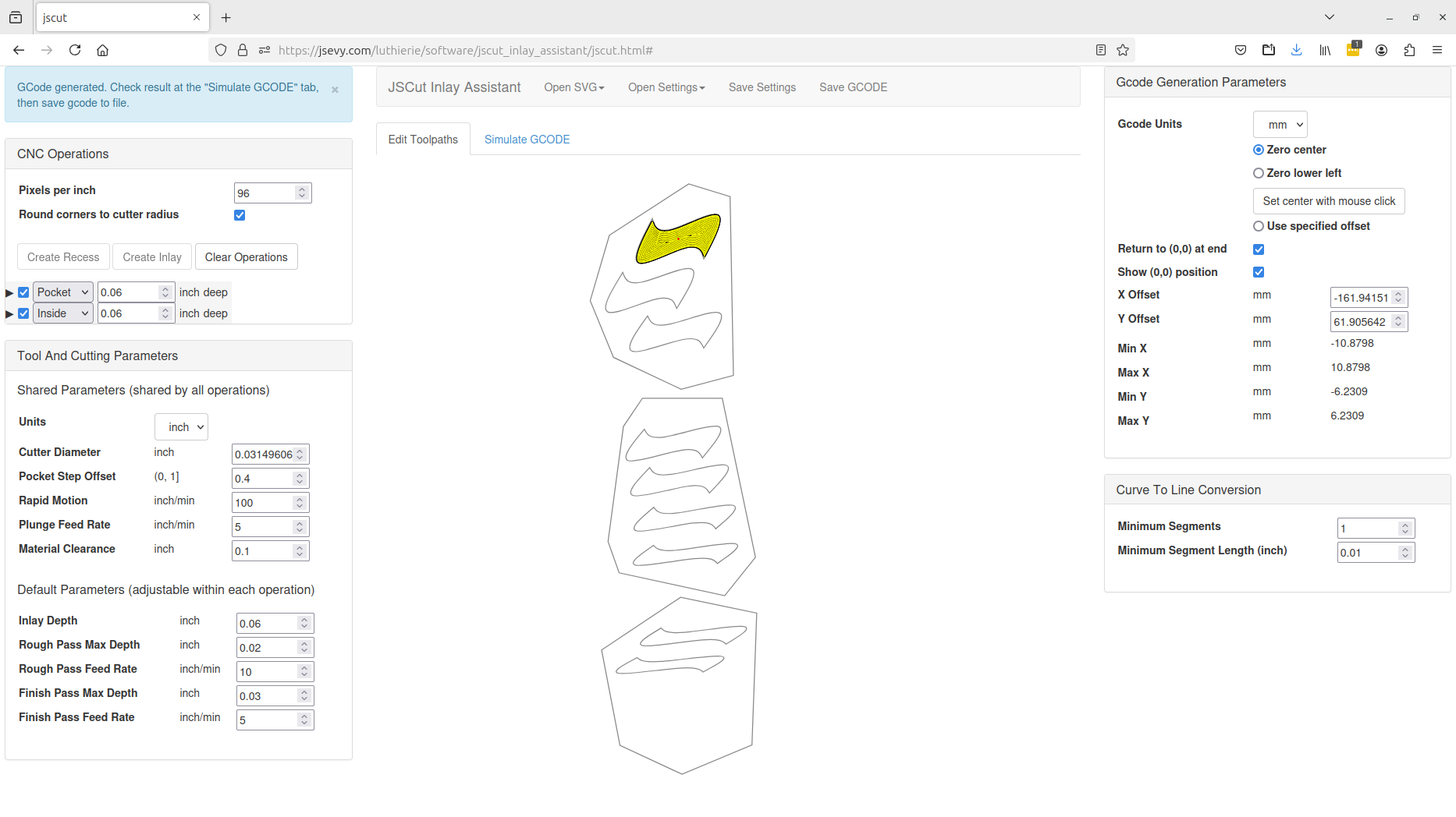
To create a recess for the inlay to go into, we need to hollow out a pocket in the peghead. JSCut Inlay Assistant will generate a path that traces the inside profile of the design, successively deepening it as necessary based on the total depth and maximum depth per pass. The path will also trace over the interior of the design in a “spiral” pattern so as to create the full recess. The screenshot below shows in yellow the path generated to create the recess into which the previously cut inlay can be inserted. Note that cutting parameters relevant for rosewood have been entered, which being softer than pearl permits a deeper cut with each pass to speed up the operation. Additionally, “Zero center” has been selected to position the zero point of the router right where we want the center of the initials to be.
As above, the cutting path can be observed with the simulator, and the generated g-code saved with the “Save GCODE” button.
Router Control and Routing
Once the g-code files are available, they must be loaded into the CNC router so it can execute the specified cutting paths. The software to do this is also used to manually control the router, moving the cutting head to a desired position, used to set the zero position (origin), discussed below.
There are a number of software packages available to provide control of the router, and most routers provide software that can be used to control that machine. This is run on a PC or laptop which is connected to the CNC router through a USB cable. Commands are sent through USB to manually control the router, as well as g-code files which are downloaded to the router for execution of the cutting paths. All of the control software packages provide the two principal functions of manual control and g-code execution; more sophisticated packages can do additional things like directly generating g-code from SVG drawings and the like. I use a freely-available open-source software package called BCNC.
The first task is to load the appropriate bit into the spindle collet. Obviously the bit diameter needs to match that configured into JSCut Inlay Assistant when the g-code was generated. I find it useful to check the runout on the bit with a dial caliper at this point and rotate the bit in the collet if the runout exceeds 0.001″ or so. Any runout in the bit will make it behave like a larger bit, producing inlays that are a little too small and cavities that are a little too large, resulting in gaps around the finished inlay.
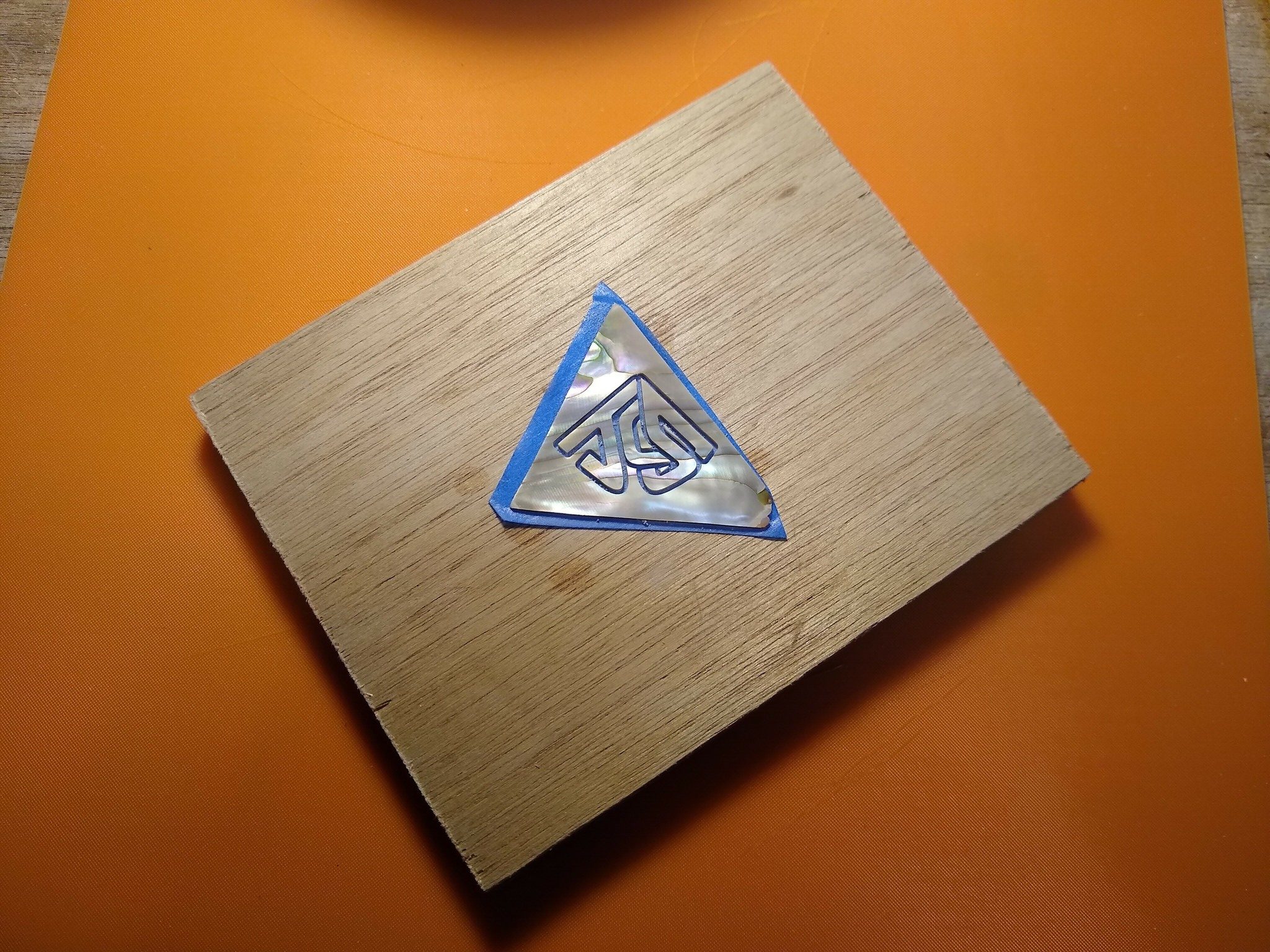
Next the material to be cut needs to be mounted on the router table. For the pocket or cavity, the piece can usually be clamped directly to the table. For the segments to be inlaid, there’s an additional complication, as the material tends to be small (shell blanks are usually about 1″ square) and the material needs to be cut all the way through (or almost all the way). These can be addressed by mounting the shell blank on a piece of wood which can itself be clamped to the table. To affix the shell to this substrate, a very useful technique is the “blue tape trick”. A piece of blue painters’ masking tape is pressed very firmly onto the bottom of the shell, rubbing it with the plastic handle of a tool to really press it in. Cyanoacrylate glue is then spread over the tape (the non-sticky side), and this is pressed onto the wood substrate. This will secure the shell firmly on the wood; even after the cutter has gone all the way to the bottom and separated the initials from the shell blank, the initials will stay put.
Once this is done it’s necessary to let the router know where the origin is. This is achieved by manually moving the cutter head with the control software so as to position the bit directly above where the center on the design is to lie, and so that it just grazes the top surface of the material. This is called “zeroing the router position.” This is pretty much a trial-and-error process, moving the head in different directions by successively smaller amounts until the bit is positioned exactly where you want it.
To get the vertical (z) zero position, move the cutter to somewhere in the middle of the material, and then slowly lower it until the cutter just grazes the top of the material. A useful trick is to put a piece of paper under the cutter, and slide it back and forth under the cutter as it is slowly lowered (by maybe 0.1 mm at a step) until you feel resistance. The paper I use is .003″ thick, which means that when resistance is first felt the cutter is about 0.1 mm above the surface; I generally lower it one more 0.1 mm step and call that z = 0.
The x and y origin positions can be set by moving the head in those directions until it is directly above the desired zero point. In the case of the pearl, this will be above the chosen corner point set in JSCut Inlay Assistant.
At this point you’re ready to start the router cutting. The appropriate g-code file generated by JSCut can be opened from the filesystem using a menu entry or button. Oddly, JSCut doesn’t include an instruction in its generated g-code files to start the spindle turning, so you’ll have to do this manually before loading the g-code (from the control software, or from an external switch on the spindle, depending on your machine). Once the spindle is turning at the appropriate RPM, the g-code file is loaded to the router using the “Start” button. At this point the router should begin moving the cutter along the path needed to cut out the inlay or create the inlay cavity. The cutting may take some time; for me it’s usually about 15 minutes to cut out the initials or rout the cavities.
Once the initials have been cut out, the process can be repeated for the pockets. At this point you’ll have matching inlays and pockets.
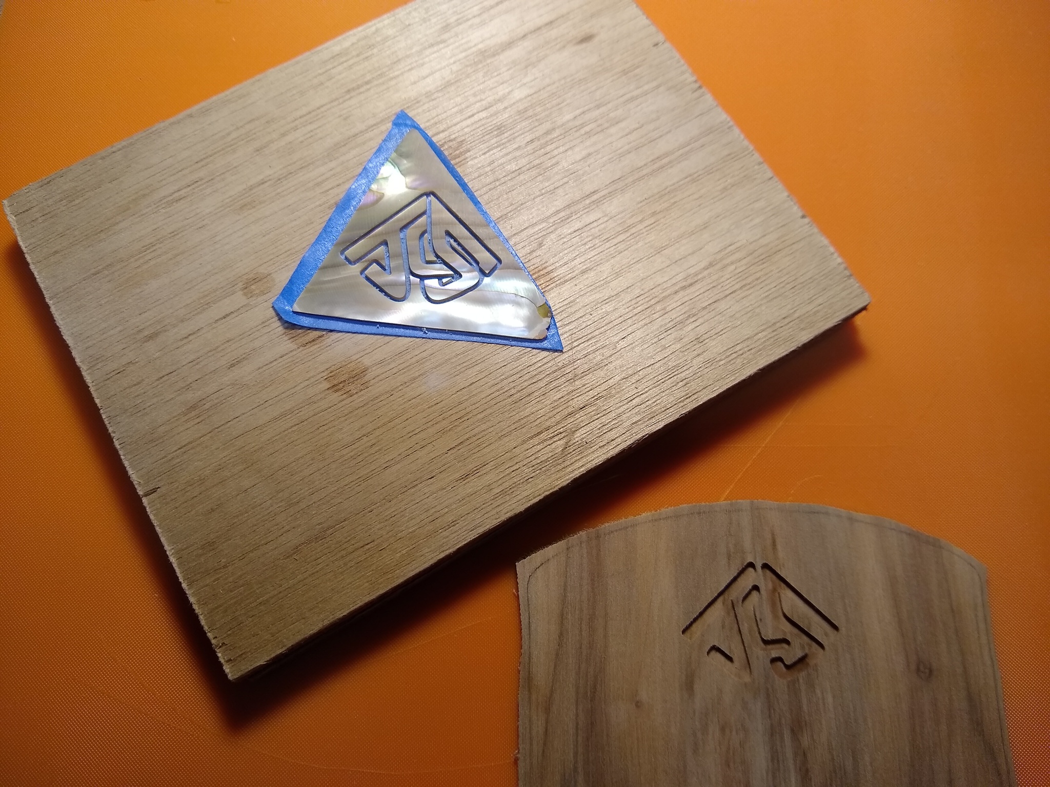
The initials can be released from the plywood substrate by either applying heat with a heat gun and gently prying, or by soaking the wood in water for a little bit. The tape is the trick, since it makes it much easier to release the cut-out pieces than if you used cyanoacrylate alone. A heat gun in particular loosens the tape adhesive so that the inlay pieces slide off easily. Any residual adhesive can be cleaned off with VM&P naptha.
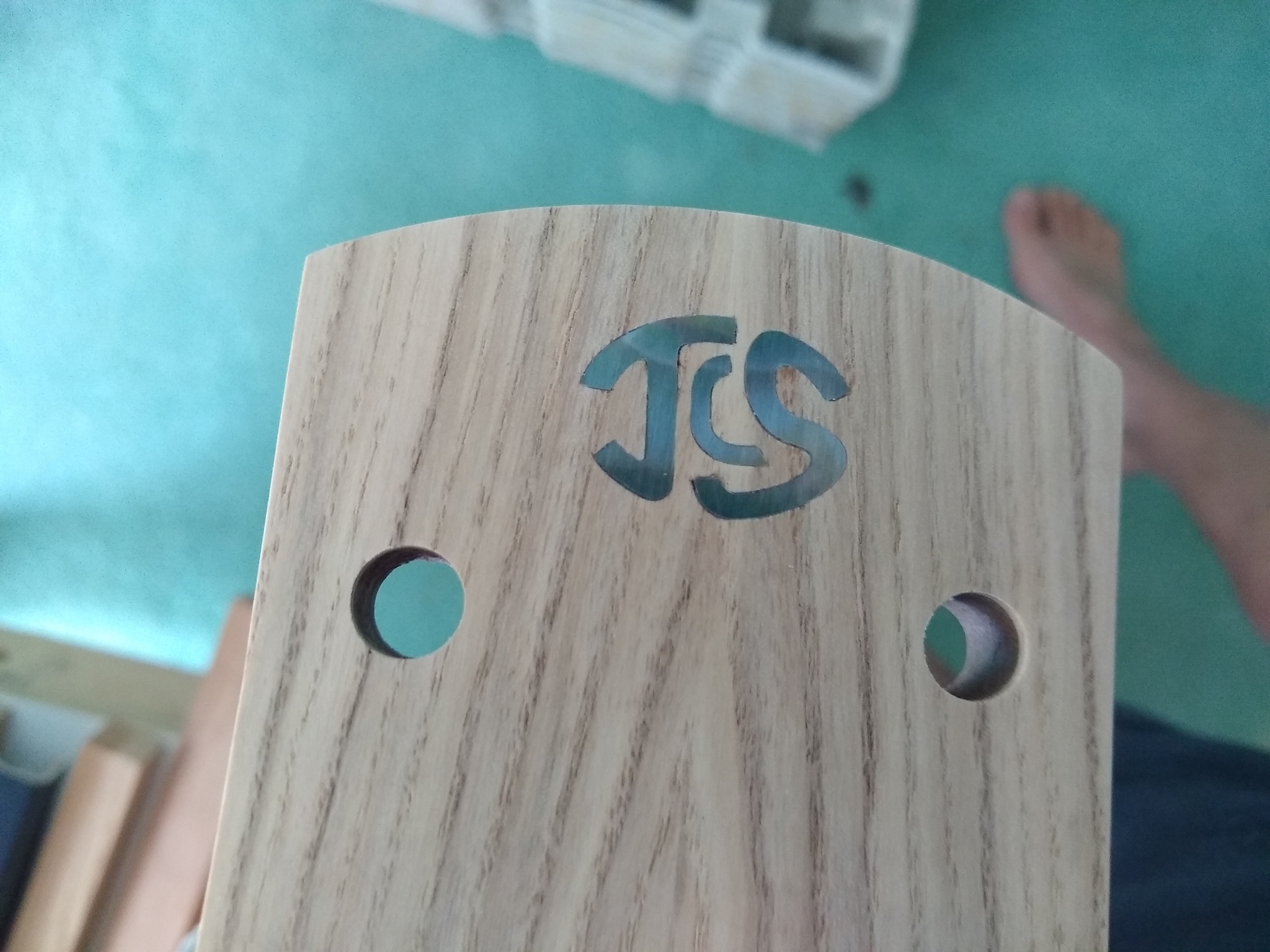
The inlay pieces can then be glued into the recess using a little cyanoacrylate glue. The CNC router should produce close-fitting inlays that shouldn’t need much touchup work to git into the recesses. I like to bevel the bottom edges of the inlays slightly so they’ll slip more easily into the recess. For this particular design, I chose to leave the corners of the design sharp (i.e., the “Round corners to cutter radius” box wasn’t checked when the g-code was generated), so I needed to do additional filing and cleanup in the corners of the inlays and recesses. When the “round corners” box is checked, this isn’t necessary.
Fret Position Markers
The other application I regularly make of the CNC router is to cut the inlays and pockets for fret position markers. Rather than using simple dots or rectangles, I design custom markers scaled to the fret sizes. The CNC router is ideal for cutting out the inlays and their pockets, speeding considerably what is otherwise a pretty time-consuming process.
There is nothing different about producing fretmarker inlays than producing those for initials in a peghead overlay. The only difference is in the layout of the inlays on the shell blanks and the positioning of the pockets on the fretboard.
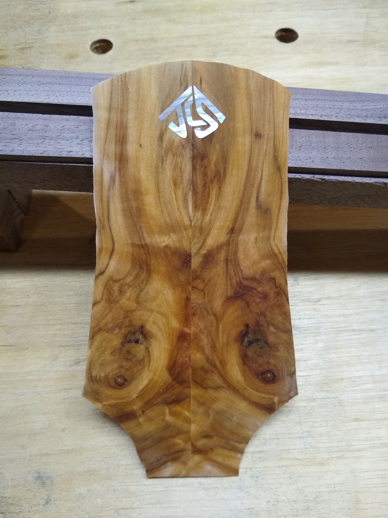
Inlays
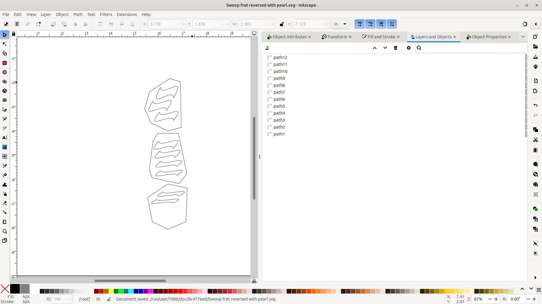
Since the fret position markers are relatively small, I can cut several from each piece of shell blank. To make this even more efficient, I lay these out together in the Inkscape SVG design program, grouped so they’ll fit onto the shell blank. I glue the shell blanks I want to use on a plywood substrate using the “blue tape” trick, then put this on a scanner and scan in the shell image. Note that it’s important to align the edge of the plywood blank with the edge of the scanner – this will be the vertical reference when the substrate is clamped to the router. I then import this image into Inkscape, and use it to position the fretmarkers.
I trace the outline of the shell pieces to give a clearer definition of the edges, and delete the image before loading into JSCut Inlay Assistant.
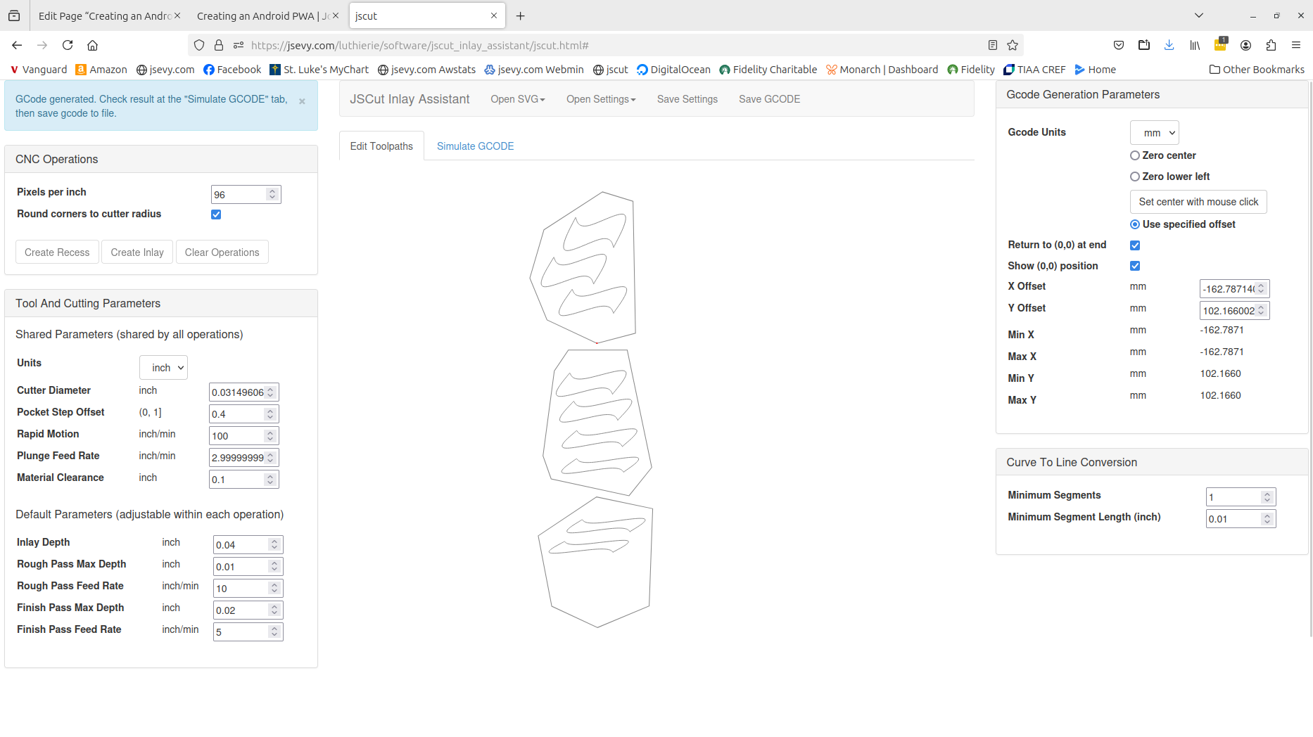
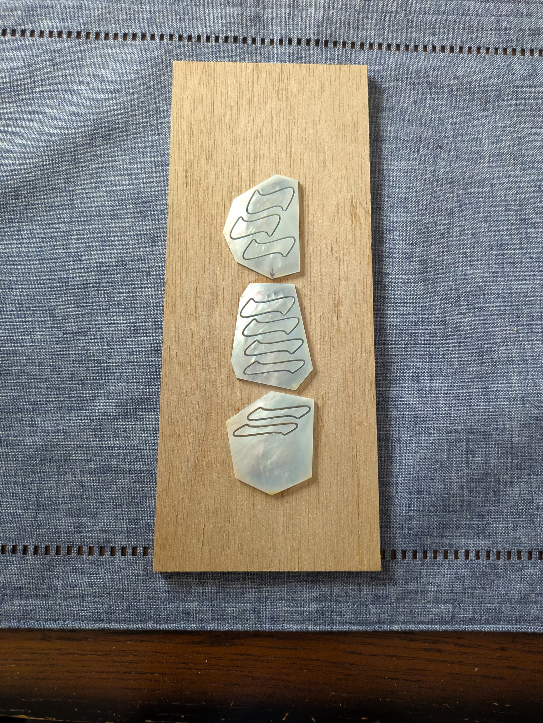
I then generate the g-code to cut out all of the inlay pieces at once from the shells mounted to the substrate. Note that the router zero-point has been chosen to be the lower corner of the top shell blank (see the red dot).
The inlays can now be cut from the shell blank just as was done for the peghead inlay. Note the “blue tape trick” used to attach the shell blank to the plywood substrate, and that the depth of cut has been set to just barely touch the tape.
Recesses
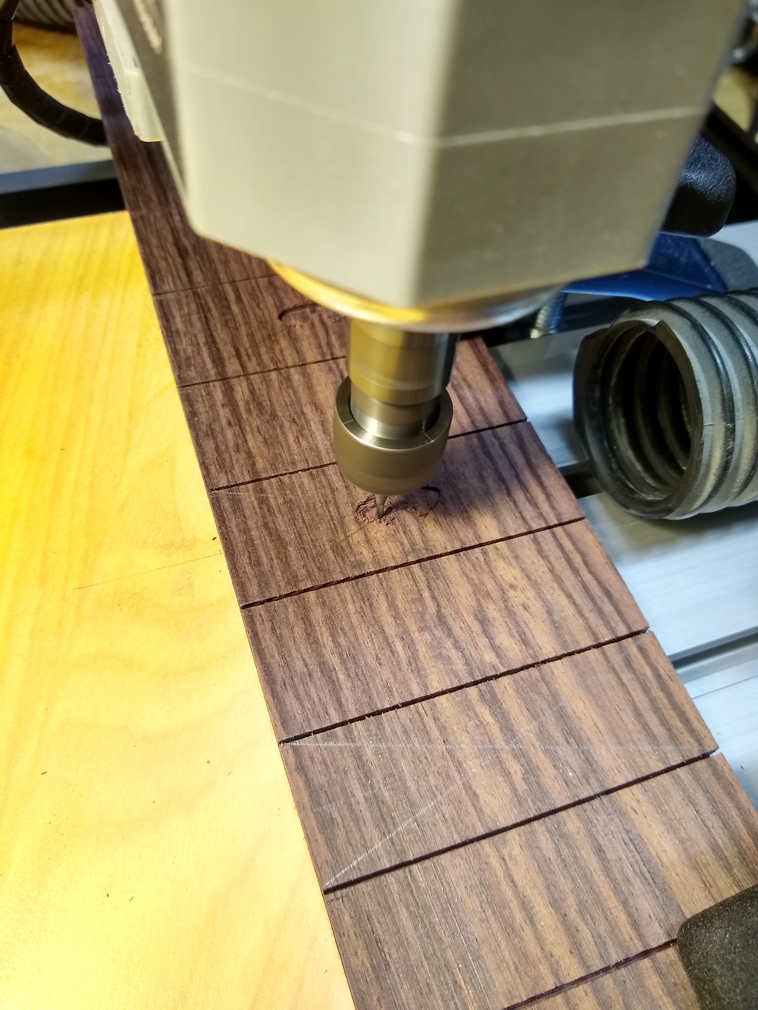
For the fretmarker recesses, it’s necessary to generate g-code for each of the recesses separately, with the g-code centered for each.
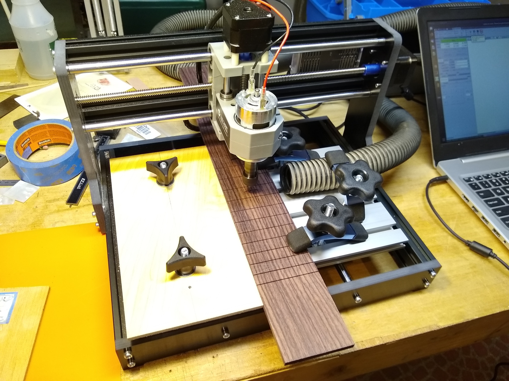
Since each recess is generated with the zero-point centered, all that’s needed to position the fretboard on the router is to locate the center of each fret rectangle, set the origin of the router for the first rectangle, and then move the fretboard into the same position for each subsequent fret. Since the fret position markers are usually located on the centerline of the fretboard, this is easily accomplished before the fretboard is tapered with a guide clamped to the router table. For each subsequent fret recess, the fretboard can be slid into position. This setup is illustrated below. In the second photo, you can see the “X” penciled on the fret rectangle used to locate the fret rectangle’s center; there’s a mark on the guide board that lines up when the fret is correctly positioned for cutting.
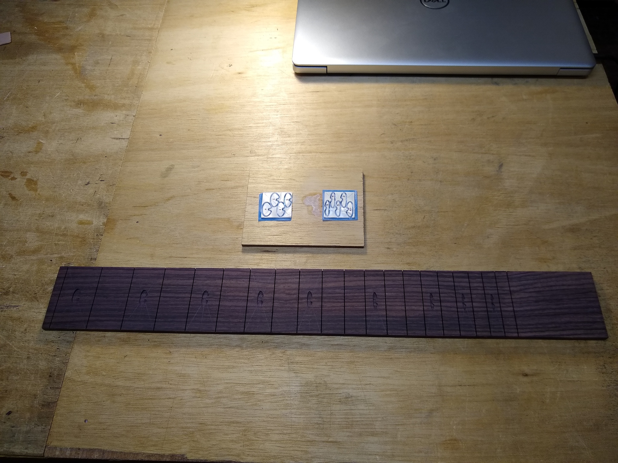
When finished, the fretboard has a complete set of recesses to receive the fret position marker inlays.
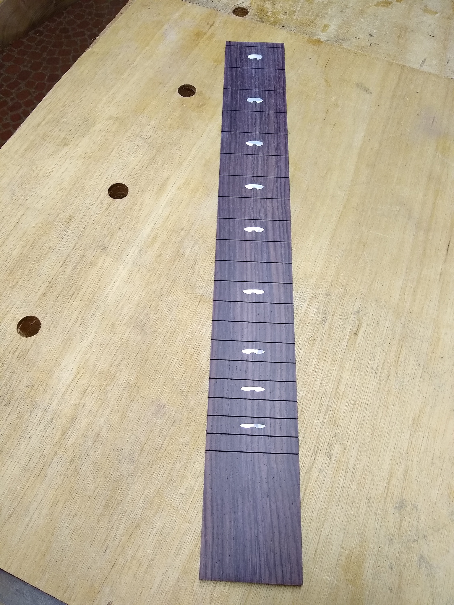
The photo below shows the result after the inlays have been glued into their pockets.
Conclusion
With a little practice to develop the technique, an inexpensive CNC router can play a very useful role in a luthier’s workshop as an inlay aide. While there are many other tasks that could be delegated to such a versatile tool, I haven’t to date used it for other lutherie operations. Like most luthiers, I enjoy the process of building by hand, and prefer hand tools to power tools whenever it makes sense. As with other power tools, I’m using the CNC router to offload a task that I find laborious and tedious, just like I use a bandsaw to resaw stock. For me, building (mostly) by hand is a pleasure in itself – the means is the end, as is the case for many craftsmen. Of course, it helps that I’m not trying to make a living doing this. My thoughts might be different if that were the case…
Appendix: JSCut Inlay Assistant – The Theory Behind The Implementation
The original JSCut program can do all that JSCut Inlay Assistant can do, and much more. Why then did I create the modified program? It seems like one could just ask JSCut to cut the inlay outline and recess pocket – both of which it can easily do – and call it a day. The problem is that if you do this naively, as I did when I started out, you’ll find that although the inlays will fit into the pockets, there will be noticeable gaps. If you measure carefully with a caliper, you’ll find that the inlays come out a bit small and the pockets a bit big. My experience was that the initial results from the CNC router, using the standard operations in JSCut, were not as good as inlays that I cut and routed by hand. This can be seen in the photo below, which is the result even after applying some mitigation attempts like tweaking the bit sizes used to generate the g-code. There are a few explanations for the less-than-ideal results, and, fortunately, some very effective solutions, which are incorporated into JSCut Inlay Assistant.
Machine Tolerances
One thing mentioned earlier was checking the bit for runout after loading it into the spindle. Any runout (essentially off-center wobbling) of the bit will make the bit seem a little bigger than its true diameter, leading to inlays a bit small and pockets a bit big. Less expensive machines often ship with pretty cheap collets, so you might find runout of a couple of thousands, which is not a problem for most work but insufficient for inlays. Fortunately, new higher-quality collets are an easy replacement, and cost maybe $20. I replaced the collet on my machine after measuring runout, and now it’s always less than 0.001″ whenever I load a bit.
Another area of machine tolerance is in the quality of the linear bearings used. You can detect this as give when you grasp the spindle (with the motor off of course) and push it forward and backward. I found there was a bit of give in mine, and replaced the linear bearings with higher quality ones. The bearings are inexpensive, but it requires quite a bit of assembly work to get the new ones in. This helped the spindle to feel more solid.
However, there’s a difference between play in the bearings and the backlash compensation built into the machine. One problem common to all machines with moveable tables and/or heads is backlash in the feed screws used for positioning. This refers to the reality that there’s always some play in a nut on a screw, and thus some dead space when the direction of the screw is reversed. This is true for both CNC and manual machines. Machinists have developed very specific techniques for dealing with this on manual mills, for example, always moving screws in the same direction to get to a setting. While the software for CNC machines can do some of the same compensation, inexpensive machines tend to use spring-loaded nut assemblies that try to take the slack out of the nut and eliminate the play. You’ll have seen these if you assembled your own machine – they’re the springs that go over the screws and push two nut segments apart. These are quite effective at eliminating play, so that there’s very little slack when the direction of a screw is reversed; the table or cutting head will immediately start moving in the opposite direction. The drawback is that because they are springs, they are sensitive to load. When the cutterhead is free and not cutting anything, they take up slack perfectly (ignoring inertia for now). But when material is being cut, the cutter is pushed forward by the drive screws into the material, which pushes back on the bit and cutterhead, which causes the backlash-compensation spring to compress a little, which introduces backlash. This can be reduced by using a slower feedrate and shallower depth of cut, but this significantly slows the operation.
Fortunately, for inlaying, there’s another approach that effectively compensates for the machine’s backlash without a large increase in cutting time.
Key Insight: Conventional Cuts and Climb Cuts
When I was experimenting and trying to get inlays with no gaps, I stumbled on an article on the CNC Cookbook website that finally gave an explanation for why there was a mismatch between the size of the inlays and the size of the pockets, leading to the noticeable gaps. The article, Climb Milling versus Conventional Milling [Sneaky CNC Tricks] by Bob Warfield, gave a good explanation of the forces on the bit and cutterhead during a machining operation, how these forces affected the cut, and how to address this. The answer lies in the difference between climb and conventional cuts.
If you’ve used a router to rout an edge profile on a workpiece, you’re familiar with the concept of a climb cut. This is when the router is moved along the edge of a workpiece such that the rotation of the bit tends to pull the router along the workpiece. In a conventional cut, the bit rotates against the workpiece, tending to resist the router being moved along the edge. For the usual case where the router bit rotates clockwise when viewed from above, you’re climb cutting when you move the router clockwise around the workpiece, and conventional cutting when you move it around counterclockwise. In fact, climb cuts are not used very often because they tend to be harder to control – there’s a tendency for the bit to grab and yank the router too quickly along the workpiece.
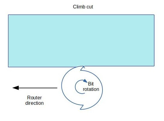
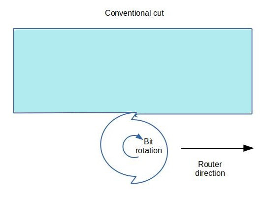
When you’re cutting a slot rather than forming an edge on a workpiece, it seems that the concept of climb and conventional cutting wouldn’t apply, but it does, and matters in an important way. If you draw a line on the workpiece and rout along this, you’re climb-cutting when the bit is to the left of the line as you move the bit forward, and conventional cutting when the bit is to the right. What you’ll notice if you try to do this free-hand (without a guide for the router) is that as the router is moved forward there’s a tendency for it to pull to the left. If you’re on the left side of the line (climb cutting), the router will tend to pull away from the line, and if you’re on the right (conventional cutting), it will tend to pull into the line. This makes some intuitive sense. As the bit moves through the material, it’s cutting at its front edge – that’s where the material is being removed. With the bit rotating clockwise as seen from the top (the standard rotation) and advancing into the material, each cutting edge of the bit will scrape away material as it rotates left to right, so the material pushes back right to left. The material is thus pushing back in a way that will push the bit to the left. For a climb cut that’s the direction away from the line; for a conventional cut that’s the direction toward the line.
This makes climb cuts and conventional cuts particularly relevant to CNC routers. If you’re cutting an outline along the outside of a design, a climb cut is when the outline is traversed clockwise – the bit is to the left of the desired profile – and a conventional cut is when the outline is traversed counter-clockwise. For cutting a pocket, it’s the reverse. As discussed above, a conventional cut will tend to pull the bit into the outline (the inlay or the wall of the pocket) while a climb cut will tend to push the bit away from the outline. With the presence of backlash, the entire cutting head (and bit) will be deflected by the forces on the rotating bit. The amount of deflection depends on a number of factors, including the strength of the backlash take-up springs, the size of the bit, the depth of the cut and the feed speed. But even with small bits, light cuts and slow feeds, there will still often be noticeable deflection, especially if you’re trying for the tight tolerances that make for good-looking inlays.
So a pocket cut using a conventional cut (bit traveling clockwise around the inside of the profile) will tend to be a bit large since the bit will be pulled into the wall of the pocket, while a pocket cut with a climb cut (counterclockwise) will tend to be a bit small as the bit is pushed away from the wall. If there were no backlash, this wouldn’t be an issue, but with backlash in the router’s drive screws, the cutting head will be deflected slightly, leading to the over- or under-sized pocket. For the inlays, the reverse is true: a conventional cut will make the inlay a little small and a climb cut will make it a little large.
It might seem then that the answer to getting a good fit for an inlay is to cut the pocket with a conventional cut and the inlay with a climb cut, at which point they’ll both be a little large and should thus fit nicely. However, because the materials for the inlay and the pocket tend to be different (shell and rosewood, say), the distortion won’t be exactly the same for the two, so this is just an approximate fit (but better than the previous approach). Fortunately, there’s an alternate approach that will produce both the inlay and the pocket to very nearly exactly the desired size.
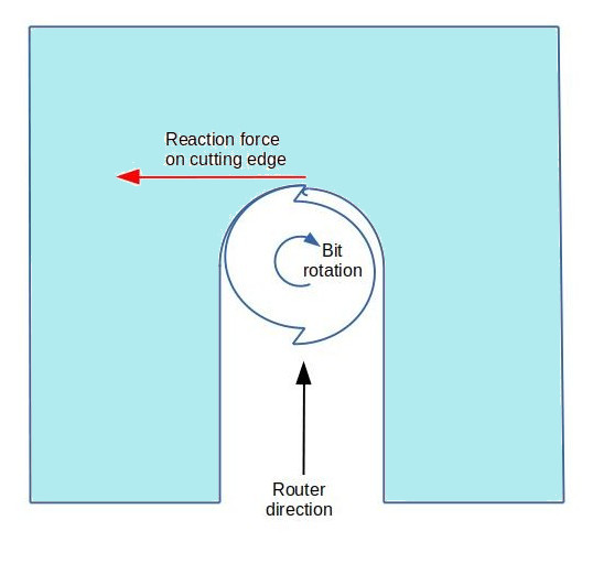
The above deflection forces on the bit apply for the case when the bit is cutting a slot – when there is material on both sides of the bit. However, if there’s already a slot, and you’re just enlarging it by shaving one of the sides, then the bit contacts and removes material mostly on the side rather than the front. The force is then mostly along the direction of travel of the bit rather than perpendicular to it. You see this with a regular hand-held router when you’re routing the edge profile – a climb cut tends to pull the bit forward along the edge more than it pushes it away from the edge (which is what makes climb cuts difficult to control). The same applies to the CNC router – there’s less tendency to pull the bit into the design or push it away, just some pressure tending to impede the bit’s forward motion (conventional cut) or pull it forward (climb cut). While this still deflects the cutting head, it’s in the direction of travel, which just means the bit lags or leads a little along the profile and doesn’t affect the overall dimensions of the part.
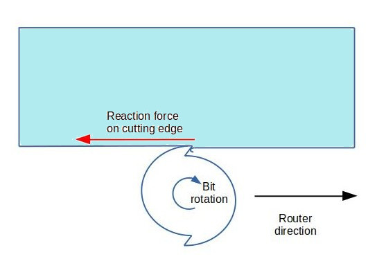
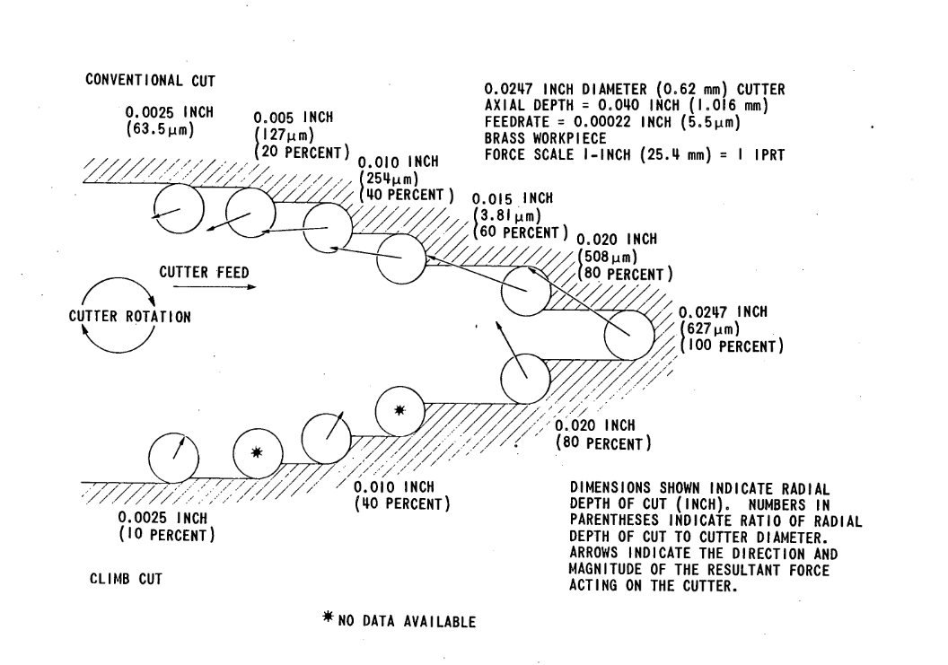
The following illustration from the publication Fabrication for Precision Mechanisms by L. K. Gillespie (1980) (and reproduced on the CNC Cookbook website) shows the reaction force the material imparts to the bit for various combinations of cutting depth for both conventional and climb cuts. As you can see, the heavier the cut taken off the wall, the more the reaction force becomes like that for a fully-enclosed slot cut. Interestingly, the direction of the force on the cutter for a light trimming conventional cut is seen to slightly away from the wall, not becoming exactly parallel until the cut reaches 40% of the cutter diameter. However, the force for a light shave is very small, so unlikely to deflect the cutter much.
Thus the solution to getting a cut that’s exactly along a design profile is to use a combination cut:
- Rough cut using a climb cut
- Finish cut using a conventional cut
The initial climb cut will leave a little extra material on the wall of the cut, which the final conventional cut will shave off right to the line. This complicates the process a little bit in that you need to configure two sets of g-code for each component. And since there are two cuts needed for each piece, it seems this would double the length of time it takes to cut each inlay and pocket. However, because the final conventional cut is just a cleanup, shaving a few thousandths of an inch off the wall, this can be done in just one or two passes, so the additional time is minimal. Additionally, for the inlay recess, the final cut just needs to run around the inside wall of the recess, not the interior.
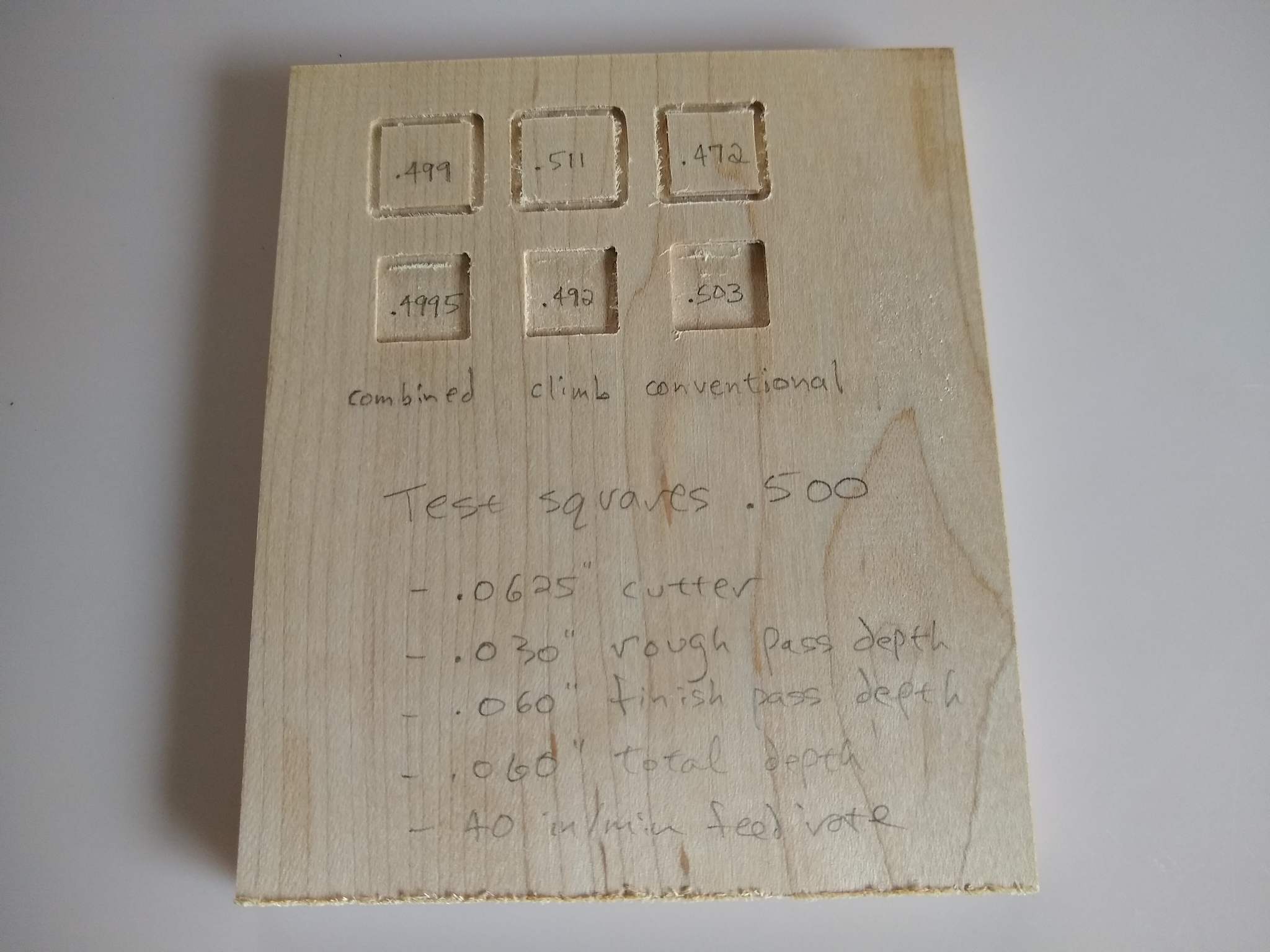
The difference in results is remarkable, as can be seen in the following photograph, in which test squares measuring exactly .500″ have been cut into maple using climb cuts, conventional cuts, and the combined rough-climb finish-conventional approach. You can see that using just conventional cuts would leave gaps (too-large pockets, too-small infills), using just climb cuts would result in too-large inlays and too-small pockets, while the combined approach produces inlays and pockets that are almost exactly the desired size. It’s worth noting that this was cut using a very rapid feed rate (40 in/min), and still produced excellent results for the combined cuts.
One interesting note is that while the straight climb and conventional cuts are in general quite inaccurate, the conventionally-cut pocket is not too far off. This results from the offset used in cutting the pocket – the distance the cutter is offset each time as it cuts out the interior of the pocket in a pseudo-spiral. The offset used was 40% of the diameter of the cutter, which is identified as the “sweet spot” for conventional cuts in the cutter force diagram above. Thus it’s possible to get reasonably accurate results for the pocket using just the conventional cut. But really, there’s no reason not to use the combined approach to get truly accurate dimensions.
Refined G-Code Generation Process
Thus the refined process for generating g-code for tight-fitting inlays is the following.
Inlay
- Generate an outside path that’s a climb cut, using the usual depth and feed rate settings for the material
- Generate an outside path that’s a conventional cut, but set the maximum cut depth to the full depth of the inlay
Recess (Pocket)
- Generate a pocket path that’s a climb cut, using the usual depth and feed rate settings for the material
- Generate an inside path that’s a conventional cut, but set the maximum cut depth to the full depth of the inlay
This can be done in the original JSCut, but it’s a bit tricky as you have to select the right options for each of the operations, including things like setting the cut pass depth to full depth for the finish cuts and making sure to re-center the g-code origin each time. To make this easier and less error-prone, I created JSCut Inlay Assistant, which is a light customization of JSCut that performs exactly the above operations to create g-code for inlays. It’s nowhere nearly as flexible or capable as the original JSCut, but it simplifies those operations needed for creating inlays.
Appendix: Using JSCut to Generate Climb-Conventional Combination Cuts
JSCut Inlay Assistant makes it easy to generate the sequence of operations needed for optimal inlay fit. However, if desired, this can also be done with the original JSCut, but requires additional steps and generates separate files for each operation. This process is described below, more for informational purposes than as a recommended approach.
To specify climb or conventional cutting, JSCut has a drop-down when you select the operation (pocket, outside, inside) that allows you to specify the direction of the cut as climb or conventional (the default is conventional). Here the rough climb cut is specified for the initials outline.
Thus you can generate two g-code files, one for the initial climb cut and one for the finish conventional cut, where for the latter the maximum depth of cut per pass can be set to the full (or half) material depth. Remember to center each using the “Zero center” selection on the right panel so they will be aligned to the same center point on the design. Thus you’ll have saved two g-code files, which you should label so you’ll know which is which (say, “inlay_climb.gcode” and inlay_conventional.gcode”).
The inlay is then cut using two router operations: the g-code for the climb cut is executed first as described earlier, and then, without moving the shell blank or changing the router origin, the g-code for the conventional finish cut is loaded and executed.
The inlay recess is cut similarly in two operations, using the two g-code files created for the recess: the pocket g-code is executed first, and the inside finish cut g-code is executed second.
Combining Operations
While it’s not a big deal to have to load g-code twice for each inlay component, there are a couple ways you can work around having to do this, and work with just one combined g-code file. Note that this is not at all necessary, just a convenience, and has some caveats, so might not be worth the trouble if you’re a relative newcomer to CNC machining.
First, you can in fact edit g-code files using any text editor of your choosing, and can thus combine two together by just copying the second file and pasting the contents at the bottom of the first. However, there are some significant caveats to this. First, you want to make sure you don’t miss of alter any of the content. Each line is an instruction to the machine, and if you leave one out or change what it says you will not be happy with the result – and this can even be dangerous if it instructs the machine to move in an unsafe way!
Second, there’s a quirk to JSCut that requires tweaking to the resulting file when you combine two in this way. Oddly, JSCut does not turn on the spindle rotation as part of the code in the file – you have to do this manually before starting the execution of the g-code, as mentioned earlier. But it does include machine code to turn off the spindle at the end of the file. Thus if you just combine the two g-code files for a cut – say, the climb-cut pocket followed by the conventional inside cut, the router will cut the pocket, turn off the motor, and then start to (try to) cut the inside profile without turning the motor back on! This will clearly not work well. So if you combine these two files into one, you then have to locate the specific machine code line to turn off the spindle and cut it out. This is probably not something that someone not familiar with g-code should be attempting, so I’d stick with loading and executing two separate files.
Alternatively, you can get JSCut to include more than one operation in a single file – for example, the pocket climb cut AND the conventional inside cut. The catch is that the max pass depth and feed speed apply to all of the operations in a file – you can’t set a different pass depth for the outside cut than is used for the pocket cut. Thus the outside cut will proceed more slowly as it will use multiple passes at shallow cut depths, rather than a single (or a couple) passes to do the finish shaving. This isn’t a huge drawback, but does increase the time to cut the recess and double the time it takes to cut the inlays.