My original source of instruction and inspiration for making flat-top steel string acoustic guitars was the wonderful book by Irving Sloane on the subject [1]. His encouraging, well-thought-out approach to constructing an acoustic instrument was all I needed at the time to become engrossed in the intricacies of turning slabs of lumber into (usually) vibrant musical instruments; I wonder how many other luthiers were first turned on by this great manual! Of course, I modified some of his procedures right off the bat (like incorporating a tapered sliding dovetail for the neck-to-body joint), and adopted other techniques that seemed to work better for me as time went on. But I still haven’t improved on some of his jigs and techniques to this day, in particular, his unique rubber-band clamping system for joining the top and back to the sides of the instrument. I’ve found this system guarantees positive location and squareness of the sides to the top and back, and produces all the pressure desired, wherever it’s needed along the sides. The jig also permits a convenient way to correctly trim the sides to get a perfect fit on the top and back – more on this later.
However, I found the jig to be limiting in one important way. Because the bottom of the jig, against which the face of the guitar lay during all of the clamping operations, was flat, the face itself had to be flat. While this might not seem to be a major drawback for building a “flat-top” guitar, it’s important in that most luthiers now recommend using a top which is slightly arched (convex). David Russell Young recommends arching the top braces to form the top into the surface of a 25-foot radius sphere [2, p.64]. William Cumpiano and Jon Natelson recommend similarly in their comprehensive book [3, p. 150], though their system of sketching the arc with a flexible thin strip of wood (a spline) produces an arch which is not perfectly circular (more on this later).
The reasoning behind the use of such an arching is the same as that behind its use in architecture and engineering, to strengthen spans. With an arched structure, the vertical forces (downward, into the face of the guitar) are resisted by horizontal forces (in the top and braces). Essentially, to press the arched top down and flatten it out, one would have to narrow and shorten it, since, being arched, it’s slightly longer and wider than it would be (to fit between the sides) if it were flat. Thus in addition to the resistance of the top plate and braces to bending, there is their resistance to being shortened (compressed) along their length. (This is exactly the effect used by some luthiers to provide clamping pressure to join the two halves of the top. The halves are laid on the workbench with the edges to be joined placed together, with a thin strip of wood directly under the joint, forming a slight arch or “tent”. The halves are restrained from spreading by nails tacked along the outer edges, and the clamping pressure comes from the compression that results when the strip of wood is removed and the halves are pressed flat against the table.) The result is that the stiffness of the top is increased by the arching. An increase in stiffness will improve the high-frequency response of the top, making the guitar brighter, or will allow the top to be thinned further, reducing the mass and increasing the volume (loudness). The increased stiffness will also reduce the effects of humidity on the top, which tend to bow the top out during periods of high humidity and dish the top in when the humidity is low (because the top is restrained from expanding and contracting across its width by the braces glued on its bottom surface).
A guitar top will become naturally arched due to the force of the strings on the bridge, as we’ve all observed, the arch in time becoming permanently set into the top. This eventual arching is somewhat unpredictable, being different for each guitar, and often necessitates at least a change in bridge height, and at worst a resetting of the neck angle, to readjust the action. The built-in arching, by increasing the top’s stiffness, will help to minimize (though not completely eliminate) this phenomenon. It will also, however, provide for additional clearance at the bridge, allowing the saddle to be set initially a little high, whereby it can be lowered in time as the top settles, to reduce the action without requiring the bridge to be cut down or the neck to be reset. This extra clearance results because the neck angle is set so that the top surface of the neck is (more or less) tangent to the arched top surface at the edge of the guitar; if a long straightedge is placed on this neck surface, the top effectively “arcs away” from it as one goes toward the lower bout.
The arguments for using an arched top are compelling, but being stubborn by nature and not wanting to give up a great jig, I found ways to rationalize using a flat top. In particular, I didn’t like the way Young, and Cumpiano and Natelson, glued the braces to the top (and back) of the guitar, using thin splines beneath to distribute the clamping pressure to the top and a straight stiff support on top of the brace to keep its arching correct. Having several thumbs on each hand, and having used a similar setup (though with concave-arched cork-faced supports instead of the splines) to glue the braces on backs (which were arched in only one plane), I knew my patience wouldn’t survive the first set of braces. I also had concerns about the stresses that would be clamped into the top, as Cumpiano and Natelson warn, if one of the underneath splines should become slightly misaligned. And finally, I just didn’t want to give up the support and clamping system that had worked so well in other regards.
The answer lay in making an arched work-board which would fit inside the clamping jig. I ruminated on approaches to this for some time, and finally got sufficiently vexed one summer with humidity-induced bowing of the tops changing the action on my flat-tops that I decided to take the plunge. In less than a week-end, I had arched workboards for the top (arched in two planes) and back (arched in one plane), along with some subsidiary jigs that have made building a slightly arched top no more difficult than building a flat one. In addition, the back workboard has made gluing the back braces a breeze. I made the boards out of high-density particle board, and faced the arched surfaces with white Formica to give a smooth working surface and to make any errant specks of rosewood, sanding grit or other detritus readily apparent so they can be brushed away before they become permanently embedded into the face of the guitar.
To make these workboards, one needs only a router and a carriage on which the router rides to cut an arched groove. The arching on the carriage should have the desired curvature for the top (or back); more on this later. The carriage should be long enough so that the router can plow a groove unobstructed that is at least as long as the length of the guitar, and should have some provision for attaching to the workboard. I made two carriages, one for the top and one for the back, as illustrated in Figure 1. The router is used with an edge guide to keep it centered in the carriage.

Figure 1
I originally made guitars with backs arched in only one plane (across the width), the surface of the back being a portion of a cylinder. I’ve since switched to using one spherically arched, as with the face, though with a smaller radius (higher arching), to better prevent dishing due to humidity changes. To form such a singly-arched workboard for the back, the carriage is first clamped so it is perpendicular to the centerline of the workboard, and then moved parallel to itself to rout each successive groove. This produces the desired trough-shaped arch. The back workboard need not be cut to the outline of the guitar, as it isn’t used inside the jig; I left mine rectangular.
The surface of the board can now be cleaned up with sandpaper and scrapers. I glued the Formica to the arched surface using 3M High Strength Spray Contact Cement. The Formica is pliable enough, and the dishing of the top workboard small enough, so that the laminate will conform easily to the dished contour; the back workboard, being arched in only one plane, is no problem. (A mathematician would say that the back contour has a Gaussian curvature of zero; the top has a small positive curvature. Technically, to form the Formica sheet to any surface with a non-zero Gaussian curvature, it would have to be stretched or shrunk in regions. Fortunately, the top workboard’s curvature is so small that this effect is negligible. But try Formica-ing a basketball!) Any overhang in the Formica can be trimmed with a fine-toothed bandsaw or the like, and smoothed with a sander (a laminate trim bit in the router’s not so great, since the surface of the laminate is dished, not flat). Be sure to put Formica on the back surface of the workboard too, to keep humidity from warping the board and changing the arching of the top.
The amount of arching, as measured by the height at the center of the top or back, is up to the individual. As mentioned before, Young recommends a 25-foot radius for the top arching; Cumpiano and Natelson recommend an arch for the top that rises 1/8″ at the center of an 18″ span. The type of arch used, though, is worth considering, and depends partly on how the braces are themselves to be arched.
There are two somewhat “natural” types of archings for the carriage that deserve consideration. The first, and seemingly most natural, is a circular arch; this will lead to a spherical surface for the top, and a cylindrical surface for the back. The radius of the circle is very large for the slight archings used for both the top and back; for example, if the height of the top arch is chosen to be 1/4″ and the length of the top is 20″, the appropriate radius for the circular arc for the carriage would be 200″, or about seventeen feet. This will definitely try your patience if you try to draw such an arc using a nail, a string and a pencil. Fortunately, there’s a beautiful device which can be made in a flash, appropriately dubbed the Long Compass, which will do the job using a lot less room than seventeen feet. To shape the carriage arms, one can make a template with the appropriate radius arc, trace this onto the side of the arms, bandsaw them to the guideline and then smooth this surface with a spokeshave. I made the arms out of one thick piece and then ripped it in half, to ensure that the arch along both arms was exactly the same. To shape the braces for gluing onto the top, use the template to trace the arc onto the side of the brace, and then shave the gluing face of the brace to the outline using a spokeshave or disk-sander. If you use a spokeshave, it’s important (and difficult) to keep the arched face of the brace perpendicular to the sides of the brace.
While the circular arch would seem the most natural (certainly to the ancient Greeks, anyway), there’s another type of arc that directly reflects the way thin beams and plates (like guitar braces and tops) naturally bend, the cubic spline. This is the curve that is generated by flexing a thin stick (or spline) so that it passes through a specified set of points; in fact, exactly such a tool is used by draftsmen, the so-called “draftsman’s spline”. (Mathematically, the curve generated is (for small deflections) a piecewise-cubic polynomial with second-order continuity and second derivative zero at the ends. The curves used in modern computer-aided drafting are generalizations of these called parametric cubic splines, B-splines and Bezier curves.) The advantages of using a spline arch are many. First, the device to sketch a spline curve is even simpler to construct and use than the Long Compass (though you should go ahead and make the Long Compass just so you can say you have one, impress your friends, etc.) – it’s just a thin strip of wood! Secondly, and more importantly, this arch is the natural arch that the braces and top want to bend into when they’re stressed; thus when the arched brace is glued to the top, the stresses in the top will be more natural than they would be if the top were forced into the more unnatural (for it) circular arc. And finally, there’s a great jig for arching the braces to this natural spline curve that was described years ago in an issue of American Luthierie (published by the Guild of American Luthiers, Tacoma, WA), shown in Figure 2. The jig clamps a straight brace in an arched position; the arched face of the brace is then planed flat, so that when the brace is released from the jig the flat face flexes into a perfectly complementary arc!. With this jig, getting the precise “spline” arching on the brace, with the gluing face perfectly perpendicular to the sides, is a breeze. It’s worth noting that if you try to use this jig to get a circular arching on the braces, it won’t work; the arching will still be the natural spline arch, since the brace will sit up off of the circular arc on the jig when it’s put in, touching the arc only at the ends and in the middle (this is the voice of experience). However, if the arching is slight, as in the top bracing, the difference between the circular and spline arcs will be minimal, and the jig will produce very satisfactory results.
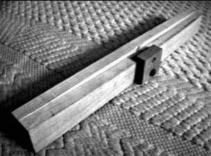
Figure 2
It’s worth noting that the edge of the top (or back), once braced into one of these curvatures, will no longer lie in a plane; if laid face down on a flat surface, the height of the edge above the surface will vary, being least at the waist and greatest at the ends of the upper and lower bouts (Think of cutting a small guitar-shaped piece out of a basketball; the edge will be wavy, sort of like the edge of a potato chip). This has ramifications regarding the joining of the top and back to the sides; the edges of the sides won’t be straight, but will be gently undulating. To get the correct profile, Sloan’s mold again comes in handy. Lay the top workboard inside the mold. Place the sides (already bent to shape and joined to the neck and end blocks, but without the kerfing) upside down into the mold, so that the edge to be joined to the top is touching the workboard. Since the edge of the top isn’t flat, the sides won’t contact the workboard all around the perimeter, but just at certain points (initially, just the ends of the upper and lower bouts). Estimate the amount needed to be removed from these points, flip the sides over in the mold, and use a spokeshave to contour the edge. Repeat this until a good fit is obtained all around. Note that the end and neck blocks should no longer be flat on the top surfaces, but angled up slightly toward the center of the guitar to make full contact with the workboard. Now glue the kerfing on; let it protrude above the edges of the sides so that it can be angled in slightly as with the neck and end blocks. When the glue has dried, shave the kerfing down to the profile of the sides, checking the angle of its top surface with a concave template having the same arching as the top (make sure the template is held so that it passes over the centerpoint of the guitar, i.e., radially). When the sides and kerfing and neck and end blocks all contact the workboard around the full perimeter, the profile of the side edge is correct. The braced top can now be put into the mold, the position of the braces marked onto the kerfing, and the recesses for the brace ends cut out. I leave the edge of the sides that will be glued onto the back straight until after the sides have been glued to the top. This allows me to use a flat piece of particle board, cut slightly larger than the outline of the guitar, on this surface of the sides, to provide even pressure and support during top gluing. This is especially useful if you’re using the Sloan clamping method, due to the enormous pressure produced by the rubber bands. (By the way, watch your face; when one of those giant rubber bands slips off the mold, it packs a wallop – voice of experience, again.) After the glue joining top and sides has dried, contour the back edges of the sides similarly, but keeping the assembly face-down in the mold and placing the back workboard onto the sides.
The only other important trick involves getting the neck angle right. Once the body is completed, I plane small flats at the neck end, on the sides and on the top. The flat on the top is to give a planar surface for the end of the fingerboard to be glued to; because of the arching, the top surface is a portion of a sphere. It also gives a reference surface for laying out the dovetail mortise. This flat need only be as wide as the fingerboard and extend to the soundhole.
The flat on the sides is to provide a reference surface for cutting the tapered dovetail mortise for joining the neck to the body, and for determining the neck angle. I usually plane this flat before I cut the binding ledge and glue the binding in place; otherwise, the binding will be narrowed at this point, though if the flat is kept small, the effect will be minor. When planing this flat, check it using a square and a long straightedge to make sure that the neck’s centerline will be parallel to the body’s.
The flat on the sides won’t, however, make a right angle with the fingerboard flat on the top, because of the top arching. Thus the top and end surfaces of the neck will not be square, but will form an acute angle. The angle could be measured or calculated, but it’s easier and more accurate just to transfer it using an angle gauge. To do this, place a long straightedge on edge on the fingerboard flat on the face of the guitar so that it runs along the centerline of the body, and overhangs at the neck end. It will not contact the face at the bridge location because of the arching in the guitar top; the space between the straightedge and face is the extra clearance that arching gives at the bridge, to help allow for future arching of the top caused by string tension. Then simply place the body of the angle gauge on the bottom overhanging edge of the straightedge, and set the angle with the blade down on the flat on the sides. This guarantees that the angle on the neck will be exactly complementary to the angle on the body, so that the top surface of the neck will be perfectly parallel to the fingerboard flat.
With the above techniques, I’ve found that an arched-top flat-top is just about as easy to build as a true flat-top. And considering the benefits in terms of stability with regard to humidity and string stresses, I think it’s well worth-while.
References:
- Steel-String Guitar Construction, Irving Sloane, E.P. Dutton and Co., NY, 1975.
- The Steel String Guitar: Construction and Repair, David Russell Young, The Bold Strummer, Ltd., Westport, CT, 1987.
- Guitarmaking Tradition and Technology, William Cumpiano and Jonathan Natelson, The Rosewood Press, Amherst, MA, 1987.