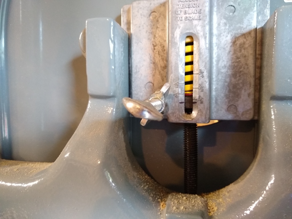
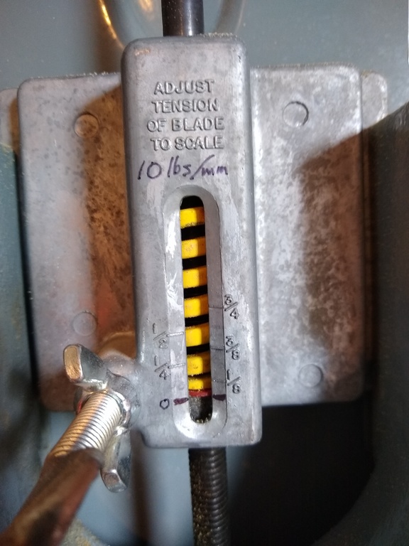
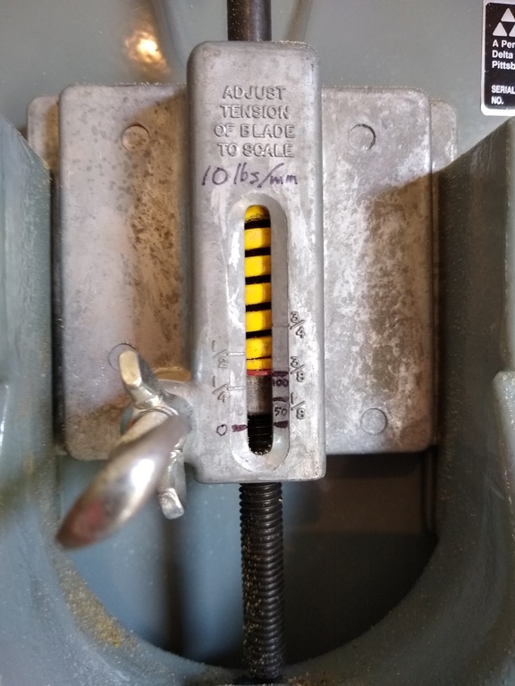
One perennial problem with bandsaws is getting the correct tension on the blade when changing it. This seems like it should be easy: every bandsaw comes with a gauge on the tension adjuster that shows how the tension should be set based on the blade width. Most work like the photo below, where the blade is tensioned by turning a knob that compresses a spring as it raises the top wheel. The red indicator shows how much the spring is compressed, and has markings that indicate how much the knob should be tightened for 1/8, 1/4, 1/2 and 3/4″ blades. The more the spring is compressed, the more tension on the blade. Seems easy enough.
Unfortunately, there are a number of problems with this approach. The settings are reputed to be notoriously inaccurate. This is exacerbated by relaxation of the spring over time, where the spring takes a permanent set and becomes slightly shorter, thus reducing the tension at any given setting. People sometimes replace the factory spring with a stiffer aftermarket spring, which increases the tension at each setting, which thus makes the tensions different from what was designed at the factory, which might be a good thing, or not if this results in over-tensioning of the blade.
Additionally, there’s a fundamental problem when blades of a different thickness are used. Each setting doesn’t determine the tension in the blade, but rather indicates the force that the spring is exerting, in pounds. The tension in the blade, in pounds per square inch (psi), is equal to the force exerted by the spring divided by the area of the blade cross-section (divided by two since there’s two strips of blade connecting the wheels). If you change the thickness of the blade, from, say, 0.025″ to 0.032″, then the cross-sectional area of a blade of any given width (say 1/2″) goes up (by 28%), so the tension goes down (by 22%) at the setting for that blade. Thus if the tension is correct for a 0.025″ thick blade, it will be too low for a 0.032″ blade.
Another issue is that different manufacturers recommend different tensions for their blades. For example, Starrett recommends a tension of 20,000-30,000 psi for their Duratec SFB blades, while Timber Wolf recommends a tension of 10,000-13,000 psi for their 0.025″ thick 1/2″ blade and 12,000-15,000 psi for their 0.032″ thick 1/2″ blade. Note that Timber Wolf recommends a higher tension for the thicker blade; but as seen above, using the same setting as used with the thinner blade will actually give a lower tension.
There are some techniques described, such as the “flutter method“, that don’t use the tension gauge at all, but rather rely on the behavior of the blade as the tension setting is changed. In the flutter method, the tension is first set to a little greater than the bandsaw default setting for the blade being used, then is decreased with the blade running and the blade maximally exposed until the blade starts to “flutter”, and then increased until it stops fluttering, and then increased a little more. In addition to being imprecise, this method just scares me. There’s also a deflection method, involving pushing on the side of the blade to see how much it deflects, and even a method using a guitar tuner. The bottom line is that none of these actually tells you the tension on the blade, which is what you really want to know.
There are bandsaw tension gauges that clamp to the blade and indicate on a dial directly what the tension is, but these are very expensive – on the order of $400. Fortunately, there’s a much cheaper way to determine the blade tension.
Force vs Tension
Bandsaw blade manufacturers specify the recommended tension range in psi for each blade they sell, but the bandsaw adjustment gauge indicates the force, in pounds, exerted by the spring when it’s compressed a specified amount. It’s thus necessary to convert from tension to force to determine the correct bandsaw setting. We can easily determine the tension in the blade if we know the force corresponding to the settings on the gauge. Unfortunately, most bandsaw manufacturers don’t label the gauge with the force exerted, instead just putting marks on where the adjustment should be for different blade widths. If we replace the default marks with marks indicating force, we will be able to ensure the blade is at the correct tension by multiplying the blade tension by the blade cross-sectional area to get the force needed, and adjusting the bandsaw gauge to the corresponding force setting.
It’s worth noting that the force needed is substantial to get typical blades to the correct tension – in the hundreds of pounds. For example, to get a 0.032″ thick by 1/2″ wide blade tensioned to 15,000 psi requires a force of (15,000) * (0.032) * 0.500) = 240 lbs. And because there are two strips of blade connecting the wheels, the total force exerted by the tensioning spring must be 480 lbs. That’s why the frames of bandsaws are so beefy – they have to withstand a lot of force.
Calibrating Bandsaw Adjuster Force
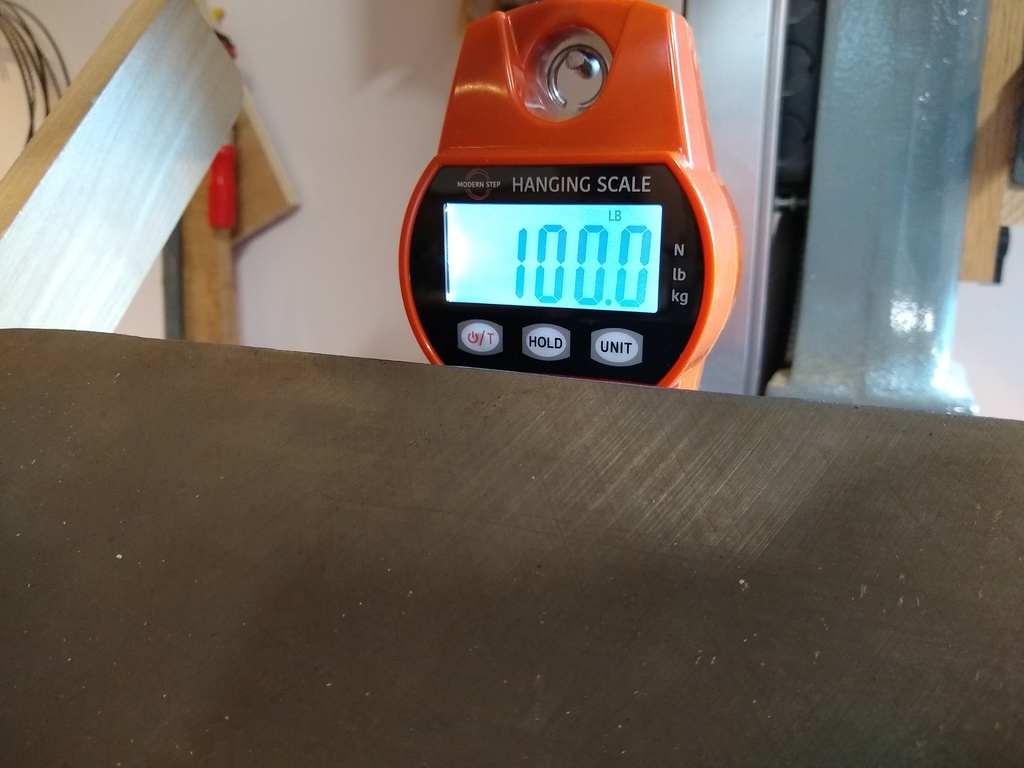
What we’re after is thus a set of marks to replace the blade-width indicators with indicators that tell what the force is that’s being exerted by the spring. The availability of inexpensive digital hanging crane scales makes this easy and accurate. The scale below is one of many available from Amazon that cost about $40 and handle weights up to 660 lbs (300 kg). Note that from the calculation above we need a pretty beefy scale to handle the forces exerted by the bandsaw spring; we’ll be going up to 200 lbs in the procedure below.
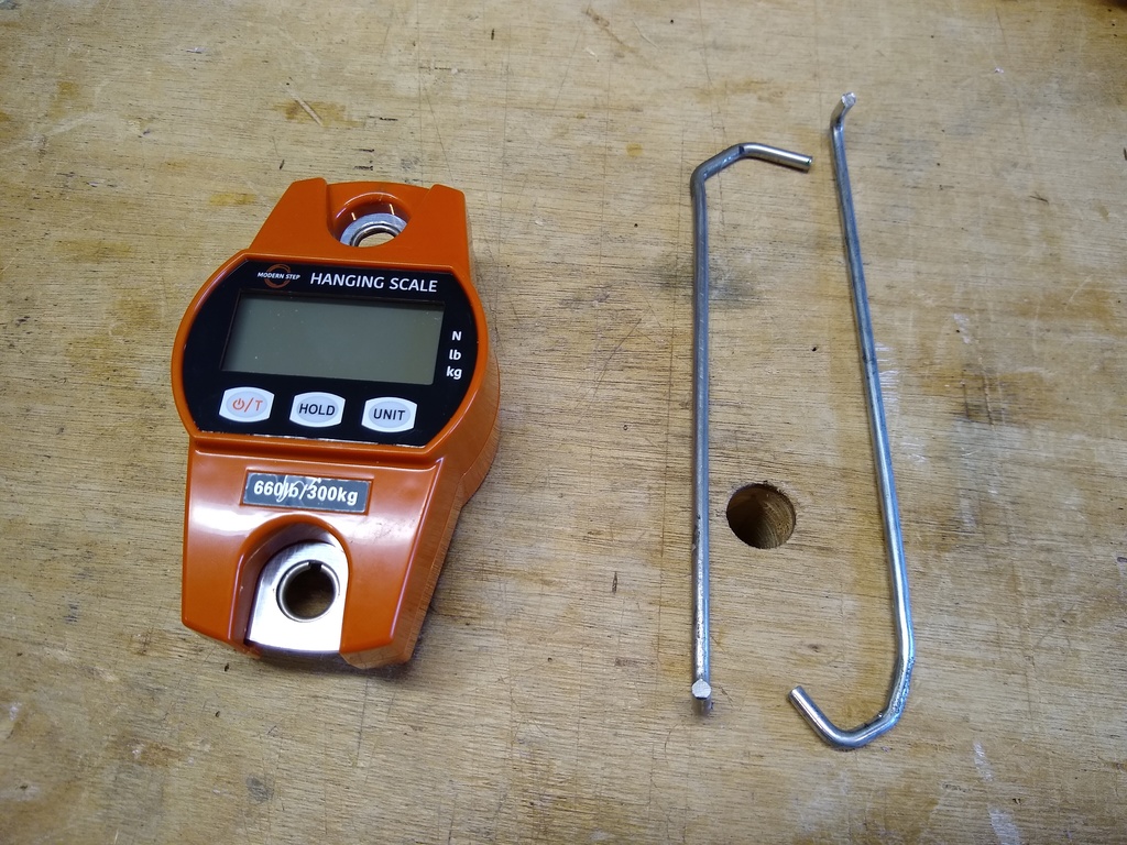
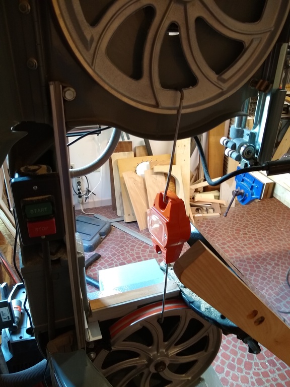
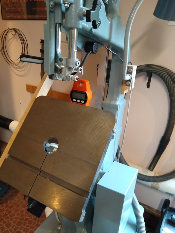
To calibrate, remove the blade from the saw, and connect the two wheels together with the hanging scale in the middle and hooks on each wheel as in the photo below. It may be necessary to tilt the bandsaw table to get it out of the way. The scale assembly takes the place of the blade, but acts along the centerline of the wheels instead of the outsides. When the bandsaw adjuster is tightened, the wheels will pull on the hooks and the scale will tell you what force the spring is exerting. You’ll need some hooks and connectors to make this work; I made hooks for each wheel out of some 3/16″ round steel stock. The hook lengths needs to be fairly precise as there’s usually limited adjusting room with the bandsaw tensioning screw – the upper wheel can be raised only about an inch before binding on the cover. The hooks will also need to be fairly robust since they’ll have to support up to 200 pounds of force. In retrospect, I would use 1/4″ stock to make the hooks if I were doing this again, to make them a little stronger – the ones I made tended to stretch a bit.
To begin, mark the zero point on the bandsaw spring indicator – the point where the spring indicator is when there’s no force applied and the spring is fully stretched out. You can do this even before the scale assembly is placed on the wheels. Ideally, this should be at a position relative to the standard default blade-width markings such that the distance from the 0 mark to the 1/8″ blade setting is exactly half the distance from the 0 mark to the 1/4″ setting. My spring had sagged a little bit so that this was no longer true (as seen in the photo at the top of the page), so I removed the spring and shimmed with a washer to make this the case. This isn’t absolutely necessary, but is a nice way to make the original markings more consistent.
With the scale assembly in place, start turning the adjuster. You’ll see the scale start to register the force in pounds as the spring is compressed. Be careful that the hooks stay on the wheels and don’t get stretched out of shape and slip off. Also, it’s probably best to line up the wheels so that the hooks are right next to one of the spokes to make sure the wheel doesn’t get deformed.
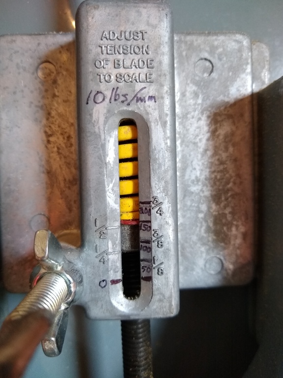
When you’ve reached a force of 100 lbs, stop and make a mark on the bandsaw spring indicator. One slight twist is to divide by 2 when you label the marks, labeling this as 50 lbs rather than 100. That’s because when the blade is in place there will be two strips of blade sharing the 100 lb force, and thus each will have half the force, or 50 lbs. You can then get the tension on (either) blade segment by dividing 50 lbs by the blade cross-sectional area, without having to then divide by 2. A small twist, but worthwhile.
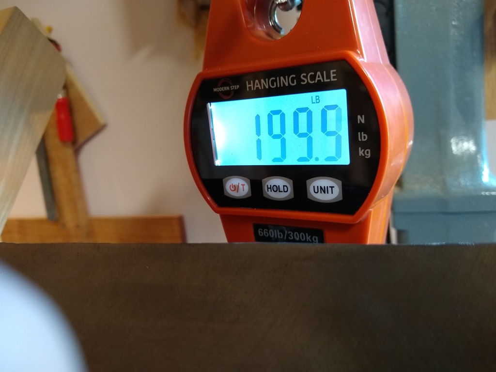
Continue tightening the adjuster until the scale reads 200 lbs and mark the indicator, labeling this one as 100 lbs. Be careful as you tighten that the hooks don’t deform and slip off the wheels – the force is enough that they could shoot across the room and possibly cause injury.
You could in principle go higher to get the marks for greater force, but I chickened out at this point; I wasn’t confident enough of the hooks in the scale assembly to put them under that much force, and didn’t want to stress the rims of the wheels any more. It’s not really necessary to go any higher anyway, since at this point you have enough information about the spring to extend the marks as needed to higher force values. The 100 lb mark should be twice as far from the 0 mark as the 50 lb mark; if not, go back and re-measure. Springs tend to be very linear (until they bottom-out and the coils all touch) – the force is directly proportional to the amount they’re compressed, so the amount the spring shortens to exert a 200 lb force will be twice the amount it shortens to exert a 100 lb force. You can thus extend the marks to indicate 150 and 200 lbs on the gauge. In fact, by dividing 100 lbs by the distance between the 0 mark and the 100 lb mark, you can determine the compression rate of the spring. For me, the distance between these marks was almost exactly 10 millimeters, so my spring exerts 10 lbs of force on each of the two blade segments per millimeter of compression. (The spring constant is actually 20 lbs per millimeter – remember we’re dividing by 2 to get the force on each blade segment.)
Converting Force to Tension
Our bandsaw now has a new scale, that shows the force exerted on the blade. To determine the proper setting for a blade, we need to know two things:
- The manufacturer’s recommended tension for the blade
- The blade cross-sectional area
The recommended tension can generally be found on the manufacturer’s website. The appendix shows the recommended tensions as published by some of the larger blade manufacturers, extracted from their documentation.
The blade cross-sectional area is easy to compute: it’s just the blade width times the thickness. But there’s a twist: the width that should be used is the distance from the back of the blade to the base of the tooth – the “gullet – not the tip of the tooth. Most blade widths indicate the distance from the back to the tip, so you’ll need to measure the distance from the gullet.
The appropriate force setting is now just the recommended tension times the cross-sectional area.
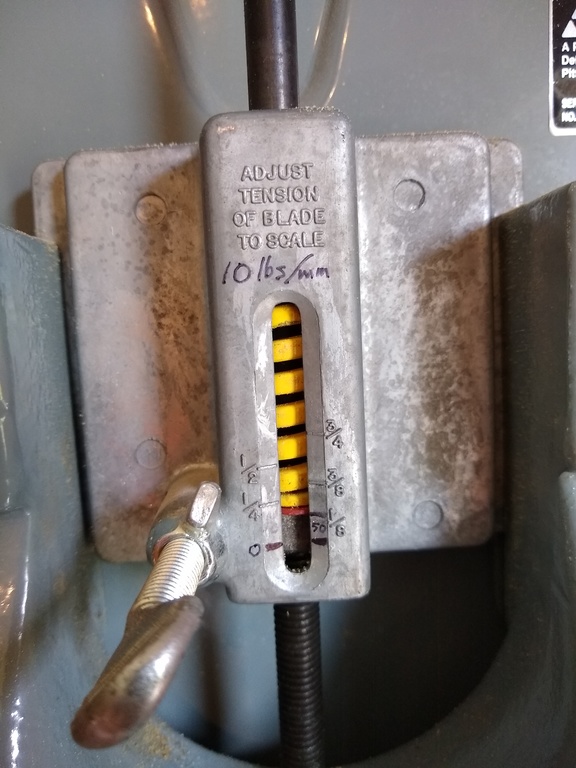
As an example, consider a 1/2″ blade that’s 0.025″ thick. Measuring the width at the blade gullet with a caliper gives 0.394″, so the cross-sectional area is (0.025) * (0.394) = 0.00985 square inches. The recommended tension for this blade is 15,000-20,000 psi, so the force needed is between (15,000) * (0.00985) = 147.75 lbs and (20,000) * (0.00985) = 197 lbs. Thus the blade will be tensioned correctly if the tension indicator is somewhere between the 150 and 200 lb settings. (It’s worth noting that for my saw, with the replacement spring and after shimming to correct the 0 location, the 150 lb setting is quite close to the default setting for a 1/2″ blade, as seen in the photo above.)
To make this even easier and quicker, I created a spreadsheet to do the math and provide handy reference tables, shown below. The columns indicate the tension desired, and the rows the width of the blade as measured to the gullet. The entries in the table then give the force setting needed. Each table is for a specified blade thickness; since I generally use 0.025″ thick blades on my 14” bandsaw, I printed the table out for that thickness and taped it next to my bandsaw. All that’s needed now is to measure the blade width back-to-gullet and look up the force needed.
Remember that these tables are for the force marking as indicated above, where the reading on the scale is divided by two to give the force on each of the two blade segments between the two wheels.
For 0.025″ blade thickness
| Force (lbs) | Tension (PSI) | ||||
| Width (to gullet) | 10000 | 15000 | 20000 | 25000 | 30000 |
| 0.10 | 25 | 38 | 50 | 63 | 75 |
| 0.12 | 30 | 45 | 60 | 75 | 90 |
| 0.14 | 35 | 53 | 70 | 88 | 105 |
| 0.16 | 40 | 60 | 80 | 100 | 120 |
| 0.18 | 45 | 68 | 90 | 113 | 135 |
| 0.20 | 50 | 75 | 100 | 125 | 150 |
| 0.22 | 55 | 83 | 110 | 138 | 165 |
| 0.24 | 60 | 90 | 120 | 150 | 180 |
| 0.26 | 65 | 98 | 130 | 163 | 195 |
| 0.28 | 70 | 105 | 140 | 175 | 210 |
| 0.30 | 75 | 113 | 150 | 188 | 225 |
| 0.32 | 80 | 120 | 160 | 200 | 240 |
| 0.34 | 85 | 128 | 170 | 213 | 255 |
| 0.36 | 90 | 135 | 180 | 225 | 270 |
| 0.38 | 95 | 143 | 190 | 238 | 285 |
| 0.40 | 100 | 150 | 200 | 250 | 300 |
| 0.42 | 105 | 158 | 210 | 263 | 315 |
| 0.44 | 110 | 165 | 220 | 275 | 330 |
| 0.46 | 115 | 173 | 230 | 288 | 345 |
| 0.48 | 120 | 180 | 240 | 300 | 360 |
| 0.50 | 125 | 188 | 250 | 313 | 375 |
For 0.032″ blade thickness
| Force (lbs) | Tension (PSI) | ||||
| Width (to gullet) | 10000 | 15000 | 20000 | 25000 | 30000 |
| 0.10 | 32 | 48 | 64 | 80 | 96 |
| 0.12 | 38 | 58 | 77 | 96 | 115 |
| 0.14 | 45 | 67 | 90 | 112 | 134 |
| 0.16 | 51 | 77 | 102 | 128 | 154 |
| 0.18 | 58 | 86 | 115 | 144 | 173 |
| 0.20 | 64 | 96 | 128 | 160 | 192 |
| 0.22 | 70 | 106 | 141 | 176 | 211 |
| 0.24 | 77 | 115 | 154 | 192 | 230 |
| 0.26 | 83 | 125 | 166 | 208 | 250 |
| 0.28 | 90 | 134 | 179 | 224 | 269 |
| 0.30 | 96 | 144 | 192 | 240 | 288 |
| 0.32 | 102 | 154 | 205 | 256 | 307 |
| 0.34 | 109 | 163 | 218 | 272 | 326 |
| 0.36 | 115 | 173 | 230 | 288 | 346 |
| 0.38 | 122 | 182 | 243 | 304 | 365 |
| 0.40 | 128 | 192 | 256 | 320 | 384 |
| 0.42 | 134 | 202 | 269 | 336 | 403 |
| 0.44 | 141 | 211 | 282 | 352 | 422 |
| 0.46 | 147 | 221 | 294 | 368 | 442 |
| 0.48 | 154 | 230 | 307 | 384 | 461 |
| 0.50 | 160 | 240 | 320 | 400 | 480 |
Conclusion
With a small investment and a little time, you can calibrate your bandsaw’s tension gauge to a much more flexible and useful scale, in pounds of force. This will help you to know that you’re tensioning your bandsaw blades correctly as recommended by the blade manufacturer, regardless of blade width or thickness or type, eliminating the guesswork that comes from using the bandsaw manufacturer’s generic settings.
You might also find, as I did, that your saw may not support all available blades at the recommended tensions. The spring on my saw at full compression exerts about 200 lbs force on the blade. That’s sufficient to get a standard 1/2″ blade (0.400″ wide back-to-gullet) that’s 0.025″ thick tensioned to 20,000 psi, which by the information in the appendix should be about right. But I have a 0.024″ thick 3/4″ Laguna Resaw King carbide blade (0.620″ wide back-to-gullet), and 200 lbs will only tension this to about 13,000 psi., which is below the recommended tension of 16,000 psi.
Appendix
Below are some blade tension recommendations as published by various journals and manufacturers.
Fine Woodworking
https://www.finewoodworking.com/2012/11/09/setting-bandsaw-blade-tension
“Bandsaw blades require tension and lots of it to consistently produce straight, uniform cuts, especially in thick or dense stock. Most blade manufacturers recommend 15,000 psi to 20,000 psi for a common carbon-steel blade. However, bimetal, spring-steel, and carbide-tipped blades are much stronger than carbon-steel blades, so manufacturers recommend a much higher tension: 25,000 psi to 30,000 psi.”
Forrest
https://www.forrestmfg.com/what-is-blade-tension/
“For carbon steel toothed blades (cutting blades) [tension] is typically 15,000 to 25,000 PSI. Slitting type blades typically are tensioned in the range of 12,000 to 20,000 PSI. In general bandsaw blades are never tensioned past 35,000 psi.”
“Overall Recommendations
Blade manufacturers typically recommend a range of blade tensions for their products. In general, it is desirable to use the lowest blade tension that will provide a satisfactory quality cut. Too little band tension and the blade may not cut straight regardless of workpiece feed speed and pressure. Over tightening the blade will shorten the life of the blade wheel rubber, bearings, and blade.”
Starrett
http://www.starrett.com/docs/other-downloadable-resources/band-saw-blade-reference-guide
| Saw Blades | Width, in | Tension, psi |
| Primalloy TM ; Intenss TM PRO-VTH; Intenss TM PRO; Versatix TM MP; Intenss TM ; Advanz TM MC7, Advanz TM MC5, TS, CS, FS and CG | ¾ , 1, 1-¼ | 20,000-35,000 |
| Primalloy TM ; Intenss TM PRO-VTH; Intenss TM PRO; Versatix TM MP; Intenss TM ; Advanz TM MC7, MC5, Advanz TM TS, CS and FS | 1-½ and greater | 30,000-40,000 |
| Intenss TM ; Intenss TM PRO-DIE; Univerz TM ; Duratec TM SFB; Band Knives High-carbon Steel | Up to ½ | 20,000-25,000 |
| Duratec TM SFB; Duratec TM FC; Band Knives High-carbon Steel | Above ¾ | 20,000-30,000 |
Timber Wolf
https://timberwolfblades.com/blade-tension.php
| Width | Minimum/Maximum tension (psi) |
| 1/8″ | 7,000/10,000 |
| 3/16″ | 7,500/10,500 |
| 1/4″ | 8,000/11,000 |
| 3/8″ | 9,000/12,000 |
| 3/8″ x .032 | 11,000/14,000 |
| 1/2″ | 10,000/13,000 |
| 1/2″ x .032 | 12,000/15,000 |
| 3/4″ x .025 | 11,000/14,000 |
| 3/4″ | 13,000/16,000 |
| 1″ | 14,000/17,000 |
Laguna Tools
(from personal communication with Morgan Helshoj)
The recommended tension for the Resaw King line of blades is 16,000 psi.
Additional Lutherie Resources