With the top braced and the sides glued to the end and neck blocks, the top is next glued to the sides. This requires that the profile of the sides – the edge where the sides will meet the top – be shaped appropriately. If the top were truly flat, this edge would itself be flat, which could be achieved by planing the top edge of the sides with a handplane. However, the top isn’t flat – it’s slightly arched into a section of a sphere. Because of this, the edge of the sides where they meet the top will be a slightly undulating curve, kind of like the edges of a potato chip.
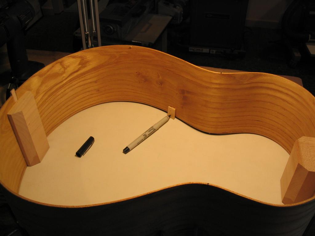
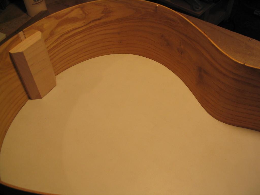
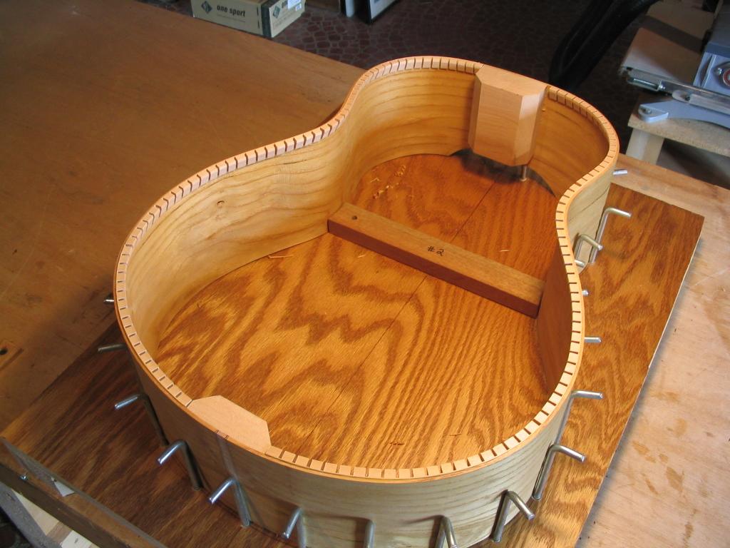
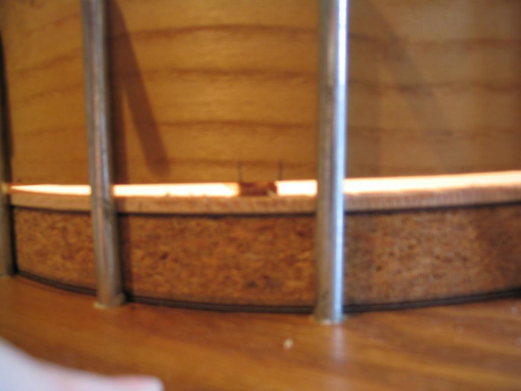
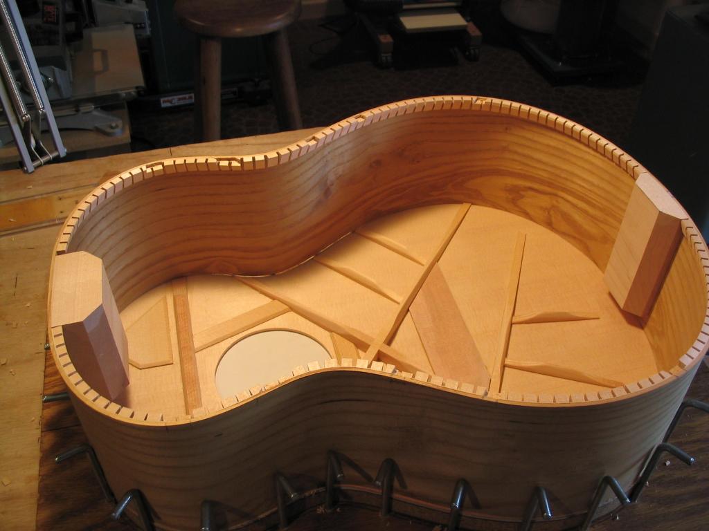
The top edge of the sides can be scribed with a line indicating the correct profile using the arched workboard used to glue the braces onto the top. The arched workboard is placed within the L-hook jig, and the sides are placed inside, with the top edge down. Because of the arching of the workboard, the sides will not sit flush on the workboard, but will touch only at the neck and tail block, as seen below.
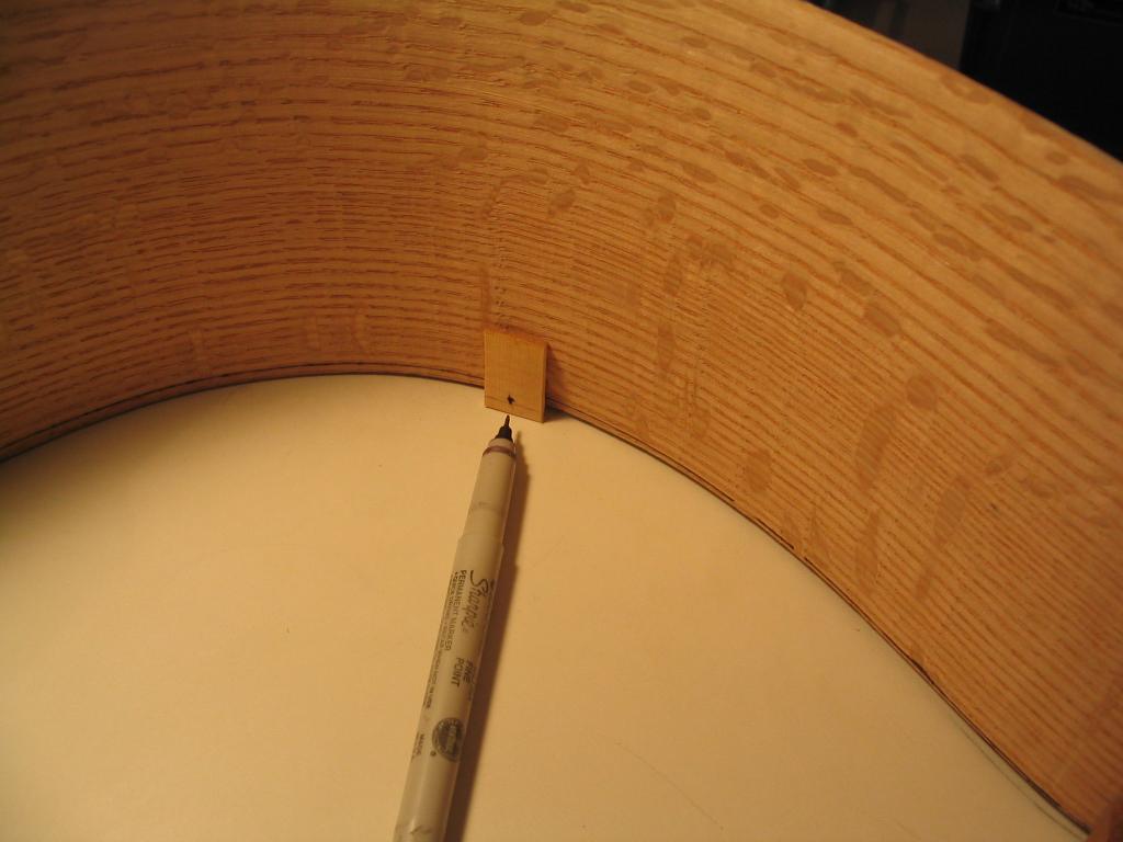
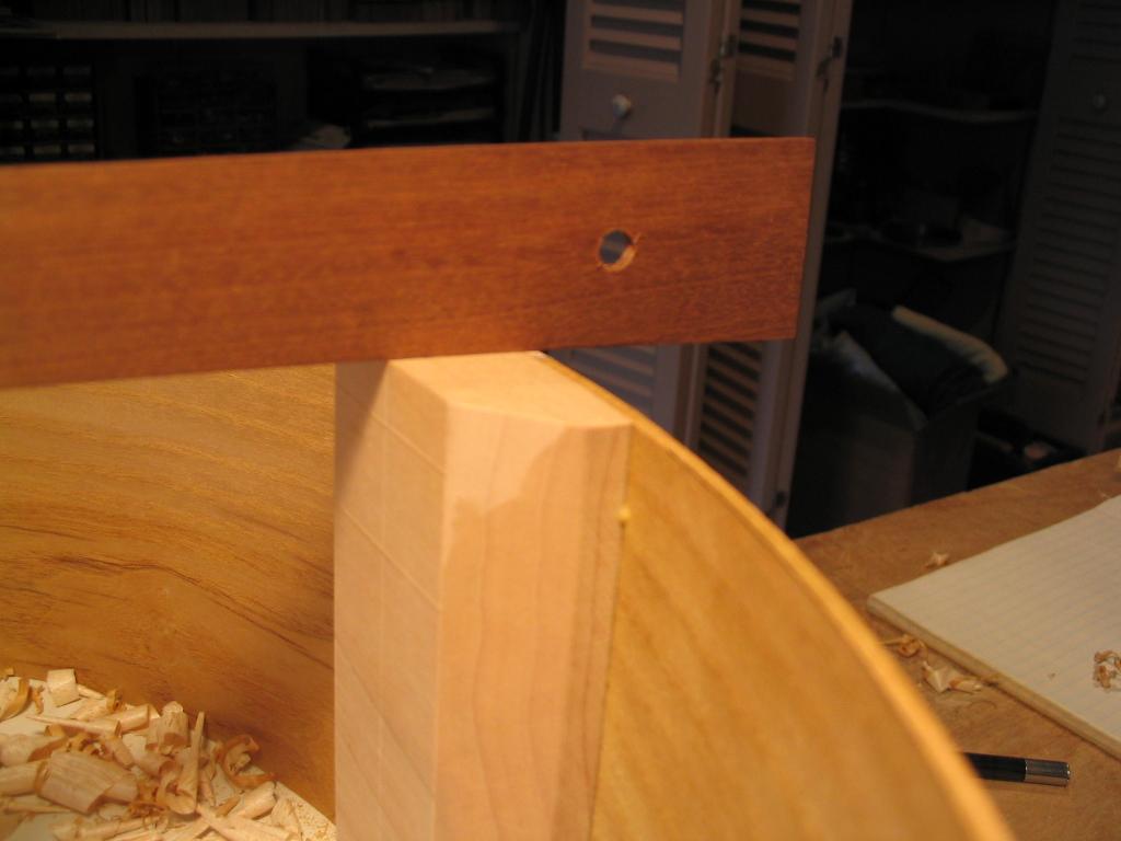
To trace theundulation of the workboard surface onto the sides, a gauge is made from a small piece of thin wood, with a 1/16″ hole drilled at a height a little greater than the maximum height the sides sit above the workboard, usually at the waist. A pencil or thin-line marker is then placed in the hole, and the gauge is slid along the surface of the arched workboard along the inner perimeter of the sides. This will scribe a line that is an equal distance above the arched workboard along the entire perimeter of the side assembly. When the edge of the side assembly is shaved to this line, the sides will sit flush on the arched workboard, and thus on the arched top for gluing.
The side assembly is then flipped upside down, and the edge shaved down to the scribed line using a spokeshave.
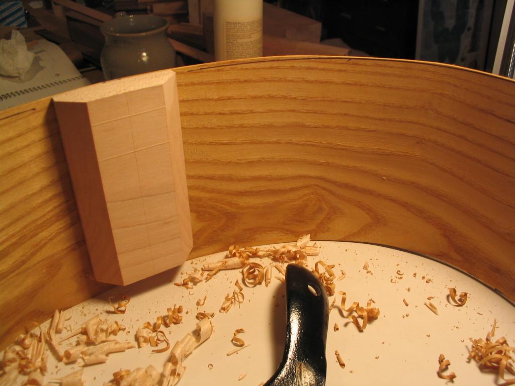
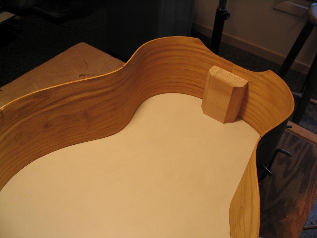
The end and neck blocks must be shaved, too, and are not flat on top, but must be angled to sit flush on the arched workboard.
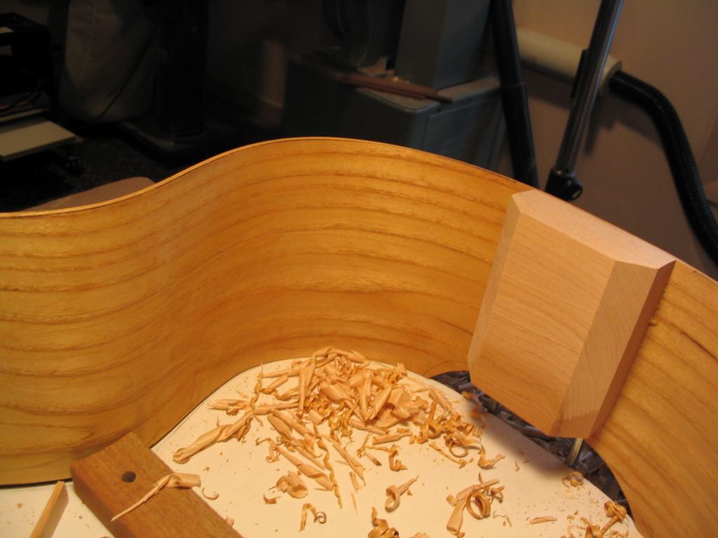
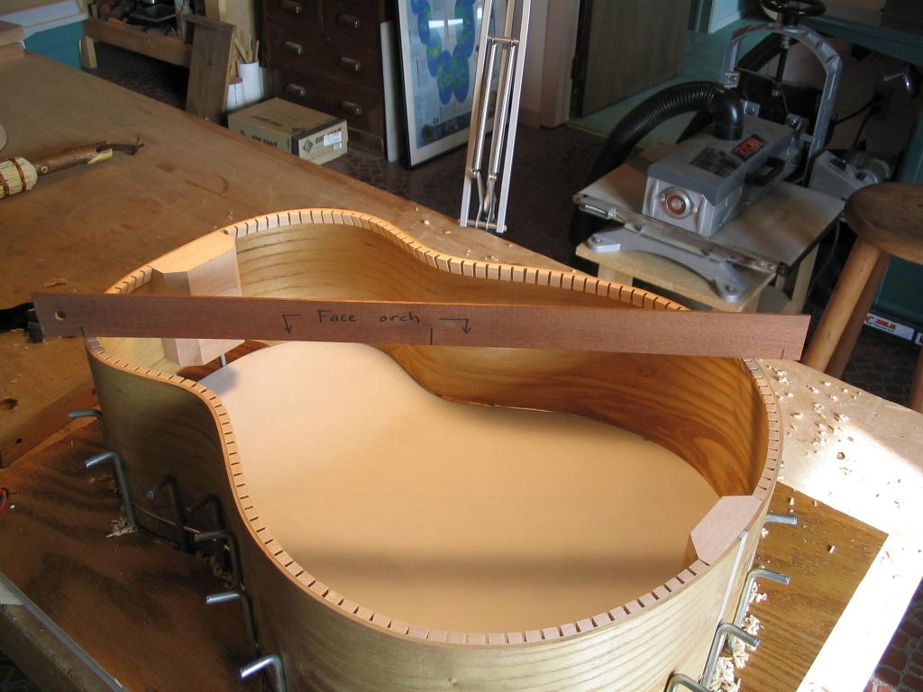
The angles of the end and neck blocks are checked as they’re shaved, using an arched template stick with the same arch as the arched workboard.

When shaving is finished, the side assembly is flipped and the edge profile checked on the arched workboard. The sides should sit flush on the workboard around the entire perimeter. If there are gaps, the sides can be further shaved.
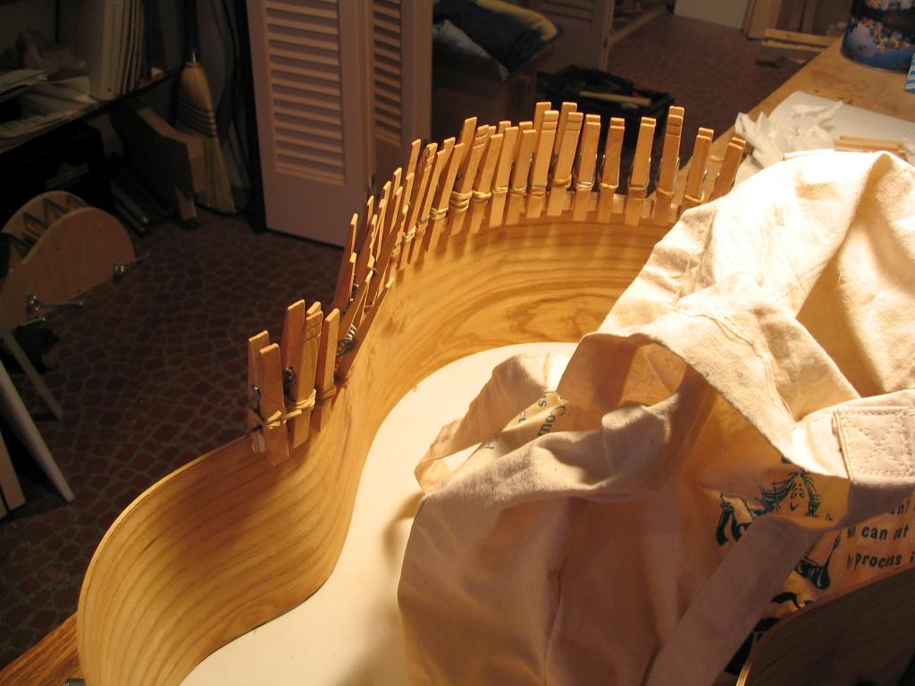
Kerfing can now be glued to the edge to provide increased gluing surface for attaching the top. I typically use kerfing that is 5/16″ wide by 1/2″ tall. The kerfing has multiple slots cut across its width almost all the way through, to make it possible to get it to follow the contour of the sides. The kerfing is glued on in short strips (maybe 4 – 6″ long), and clamped with clothespins reinforced with rubber bands to give them extra clamping force. Note that the kerfing is glued so that it protrudes slightly above the edge of the sides. This is so it can be shaved down at an angle so it will sit flush on the arched top, just as the end and neck blocks were tapered.

The kerfing is next shaved down with the spokeshave so that it is flush with the edge of the sides, but angled to meet the arch of the top. The angling of the kerfing is checked with the same arched template used to check the angling of the end and neck blocks.

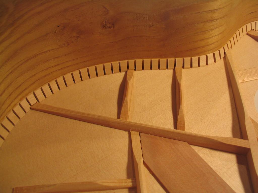
The kerfing must now be notched to accept the top braces where they run to the sides. The top is placed onto the arched workboard, the side assembly is placed on the top, and the position of the braces is marked on the outside of the side assembly.
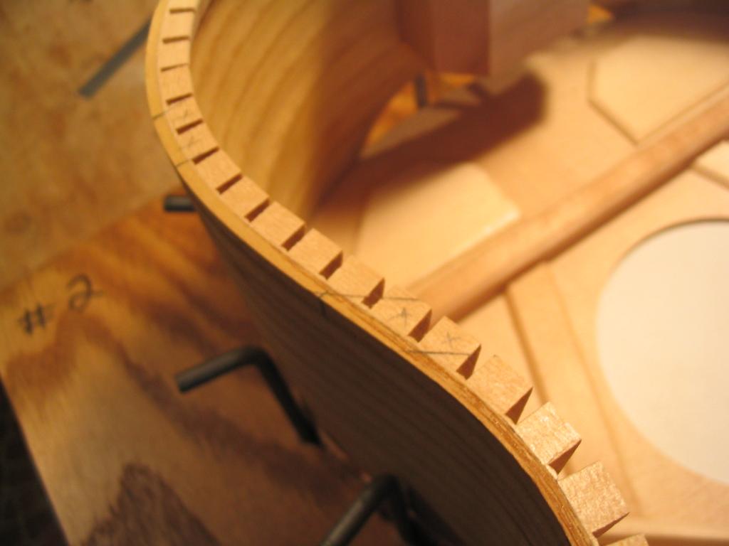
The sides are then flipped in the jig and the position of the braces marked on the top surface of the kerfing to indicate the outline of the area that must be notched to accept the braces.
The edges of the regions marked are cut with a knife and then notched with a sharp chisel. The depth of each notch is equal to the thickness of the brace where it meets the sides. A small laminate router or Dremel can also be used to remove the material from the notches. It’s also worth noting that I no longer take the trouble to stop at the sides, but rather cut all the way through to the outside. I’ve found that when the binding ledge is routed, virtually all of the side material is removed anyway, so the extra effort to cut “stopped” notches is wasted.
When the sides are inverted on the top, the braces should nestle into the notches, and the undulating side profile should sit flush on the arched top (which is on the arched workboard inside the jig).
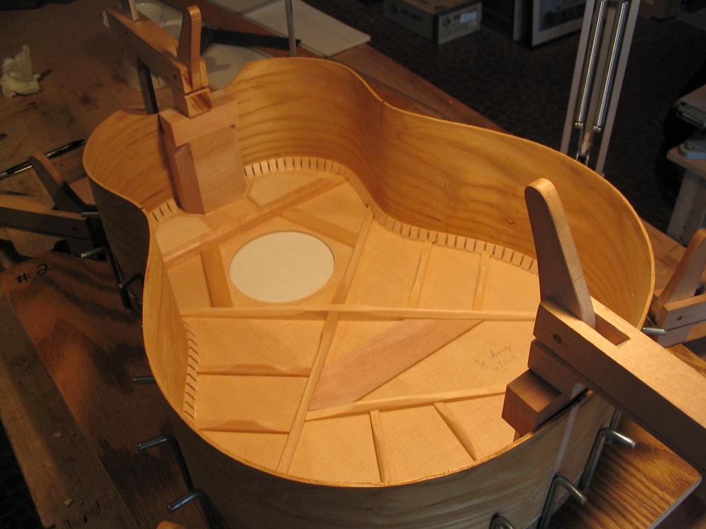
At this point the sides can be glued to the top. The sides are inverted, and a thin layer of glue is spread on the surface of the kerfing and the end and neck blocks. The side assembly is then inverted onto the top, and the end and neck blocks clamped. You should see an even bead of glue squeeze-out along the perimeter of the end and neck blocks.
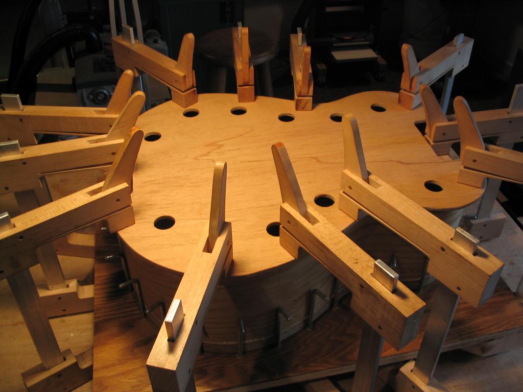
A plywood template cut to the shape of the body profile, but overlapping by about an inch all around, is then placed on the sides, and clamps placed all along the perimeter to clamp the sides down onto the top. Note the holes drilled in the template to permit inspection of the interior. Note also the cutouts at the end and neck block positions to clear the clamps already in place there.
As an alternative to the clamps, large rubber bands can be used to provide the pressure to clamp the sides against the top – this is the reason “L” backets are used in the gluing jig. The rubber bands used are number 107 bands, which are 7″ long and 5/8″ wide. These bands will put tremendous downward pressure on the side assembly as they are stretched between the “L” brackets. An example of their use can be seen in the photo below, in which the back is being glued onto the top-side assembly. The same technique can be used to glue the sides to the top, but using the plywood template over the sides rather than the back.
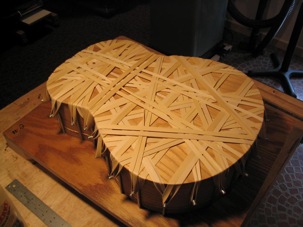
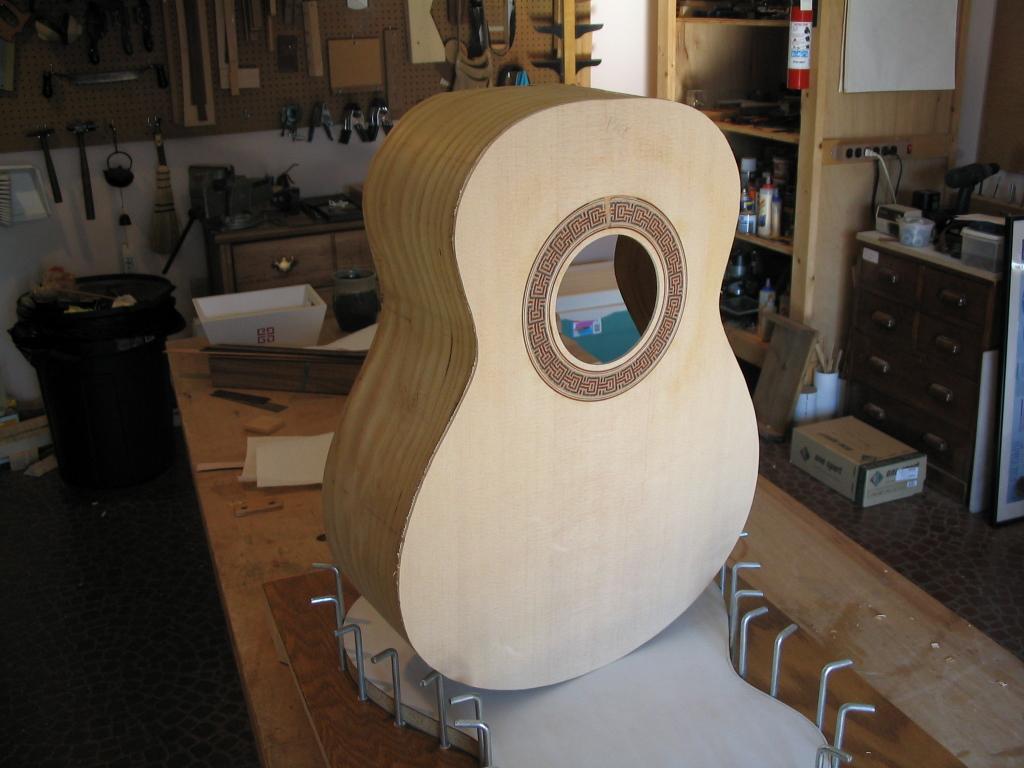
When the clamps (or rubber bands) are removed, the top is glued securely to the side assembly.
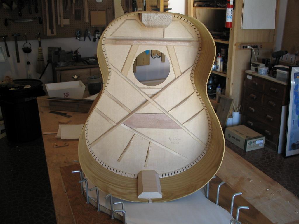
Don’t worry about the rough edge of the top; this will be removed when the body is routed to accept the binding and purfling that will run around the edge of the body.
Previous: Bending and joining the sides |
Next: Bracing the back |